1.5T Express Coil: 9E Anterior Array Cable Replacement
Prerequisites
1 Cable Removal
Procedure
- notice
- Place anterior coil patient side up.
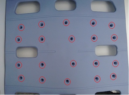
- Remove all 20 screws from the cover as shown in the Figure 1 and retain them safely.
Figure 1. 20 screws
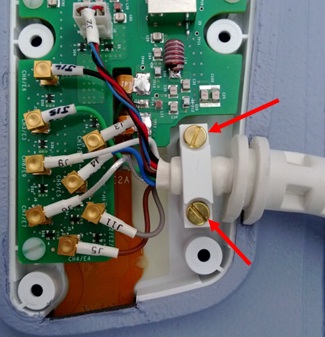
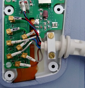
- Unscrew cable clamp. See Figure 2.
Figure 2. Unscrew cable cramp
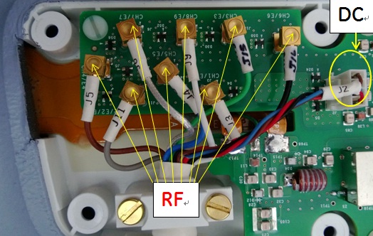
- Locate and disconnect all 8 RF cables and 1 DC cable (J2) coming
from the cable assembly. See Figure 3
Figure 3. RF Cable and DC Wire Removal
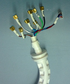
- Remove the cable from the coil. See Figure 4.
Figure 4. Cable Removal
 |
2 Cable Installation
Procedure
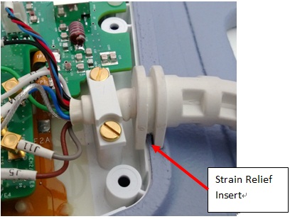
- Place strain relief in cut-out as shown in Illustration 5.
Figure 5. strain relief
- Align cable with the screw posts.
- Secure cable clamp over cable until tight with the previously
removed brass screws.
Figure 6. brass screws
- Connect the RF Co-axial connectors labeled with J3, J11, J15,
J5, J4, J16, J6, and J9 to matching (labeling) RF connectors on PCB
as shown in Illustration 7.
Figure 7. RF Coaxial Connector and DC wires
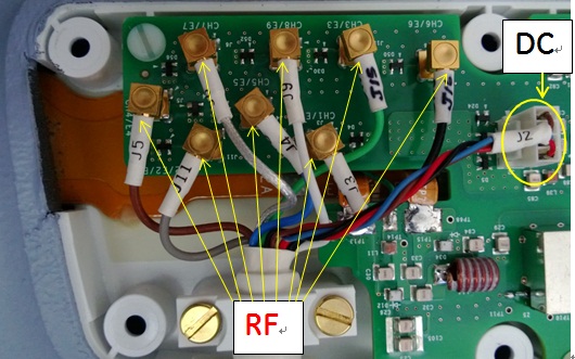
- Connect the DC wire connector (J2) to J2 on the Feedboard as shown in Illustration 7
- Replace the cover.
3 Finalization
Procedure
- Perform Express Coil MCQA Test.