MCQA Test procedure for Express Coil suit
Prerequisites
1 Head Neck Array (HNA)/Posterior Array (PA) Check
Procedure
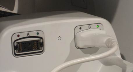
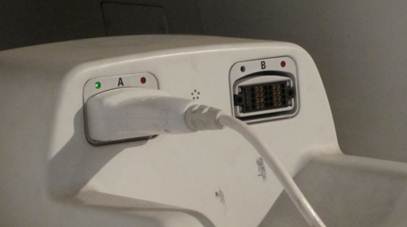
- Connect the HNA cable to Port B of MR System as shown in Figure 1.
Figure 1. Connecting the HNA Coil
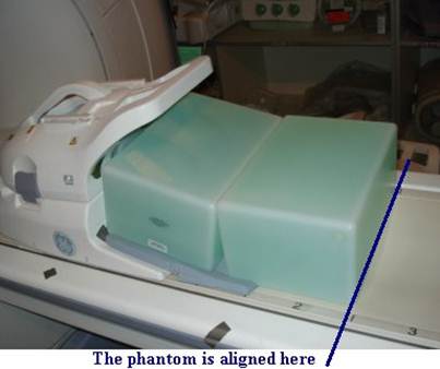
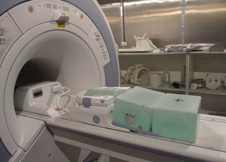
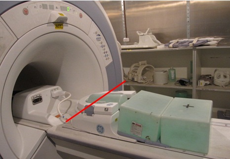
- Position the HNA and the phantoms as shown in Figure 2 and Figure 3. Make sure to use the phantom positioner and that the HNU pad is
underneath the phantoms.
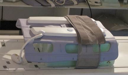
Figure 2. Positioning the Phantom and the HNA 1
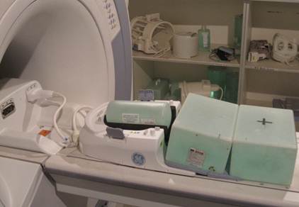
Figure 3. Positioning the Phantom and the HNA 2
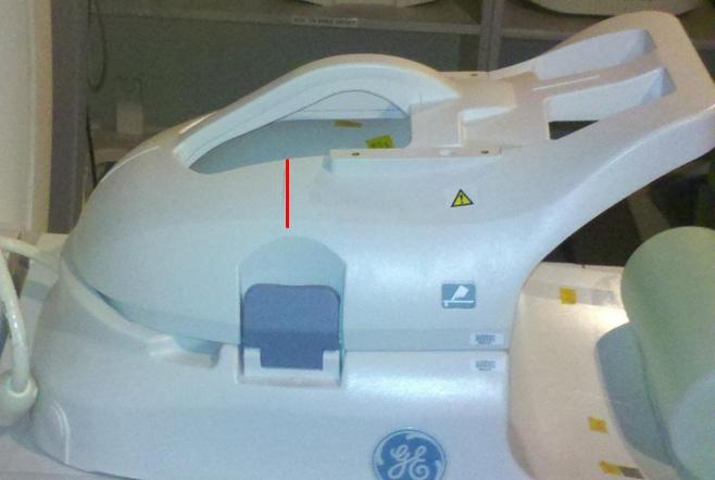
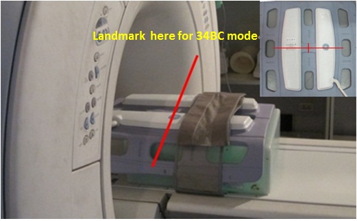
- Landmark on the HNA coil marking as shown in Figure 4
Figure 4. Landmarking Coil
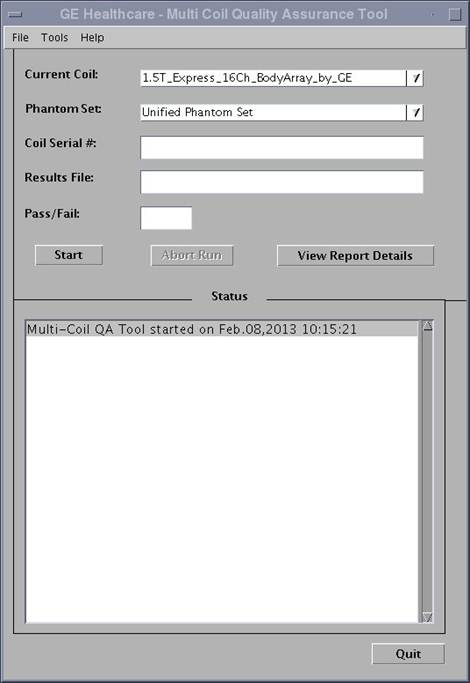
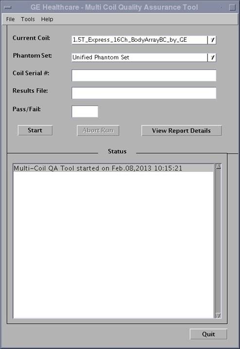
- Perform the QA Check using Multi-Coil Quality Assurance Tool procedure.
- Take note of which Test# and which Sig_Img failed(if any). To determine which coil/s has issue, refer to the matrix below.
- Remove the anterior part from HNA coil, connect the HNA adapter,
keep the phantom set as same as before, as shown in Figure 5.
Figure 5. Positioning the Phantom and the HNA adapter
- Landmark on the center of blue latch as show in Figure 6.
Figure 6. Landmarking Coil
- Perform the QA Check using Multi-Coil Quality Assurance Tool procedure.
- Take note of which Test# and which Sig_Img failed(if any).
To determine which coil/s has issue, refer to the matrix below
For coil layout, refer to Figure 16 .
- Remove the HNA Coil.
2 Anterior Array /Posterior Array Coil Check
Procedure
- Connect the AA cable as shown in Figure 7.
Figure 7. Connecting the AA Coil
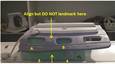
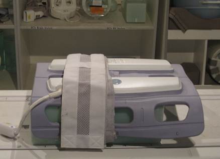
- Position the Phantoms on the cradle between marker 3 and marker
4. Make sure that the space between the phantoms is aligned with the
line between marker 3 and marker 4. Place the AA coil on top of the
phantoms. Make sure that the marker line between A, B are aligned
with the space between the phantoms. It is as shown in Figure 8.
Figure 8. Positioning the Phantom and the AA Coil 1
- Wrap the strap as shown in Figure 9.
Figure 9. Wrapping the coil
- Landmark on the AA coil marking as shown in Figure 10.
Figure 10. Landmarking Coil
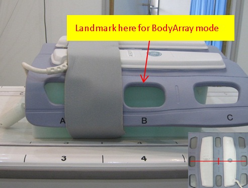
- Perform the QA Check using Multi-Coil Quality Assurance Tool procedure,
as shown in Figure 11.
Figure 11. BodyArray mode
- Take note of which Test# and which Sig_Img failed(if any). To determine which coil/s has issue, refer to the matrix below.
- Place the AA coil on top of the phantoms. Make sure that the
maker line between B, C are aligned with the space between the phantoms.It
is as shown in Figure 12.
Figure 12. Positioning the Phantom and the AA Coil 1
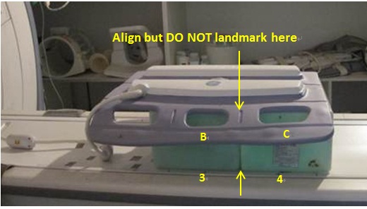
- Wrap the strap as shown in Figure 13.
Figure 13. Wrapping the coil
- Landmark on the AA coil marking as shown in Figure 14.
Figure 14. Land marking Coil
- Perform the QA Check using Multi-Coil Quality Assurance Tool procedure.
As shown in Illustration 15.
Figure 15. BodyArrayBC Mode
- Take note of which Test# and which Sig_Img failed (if any).
To determine which coil/s has issue, refer to the matrix below.
For coil layout, refer to Figure 18.
- Remove the AA Coil.
3 Element layout
Procedure
- The element layout for the 16Ch HNA coil is shown in Figure 16 and Figure 17 below:
Figure 16. Element Layout for 16Ch HNA Coil – Posterior

Figure 17. Element layout for 16Ch HNA Coil - Anterior
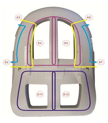
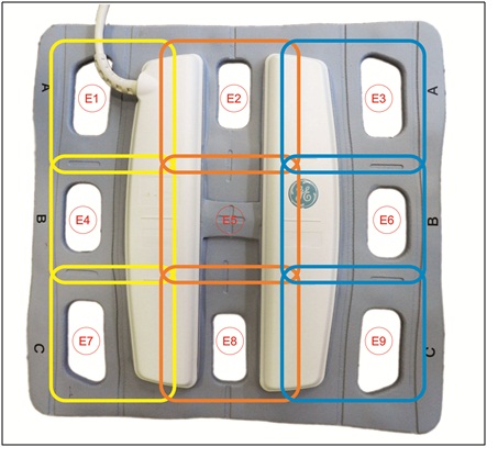
- The element layout for the AA coil is shown in Figure 18 below:
Figure 18. Element layout for 9 Element AA Coil
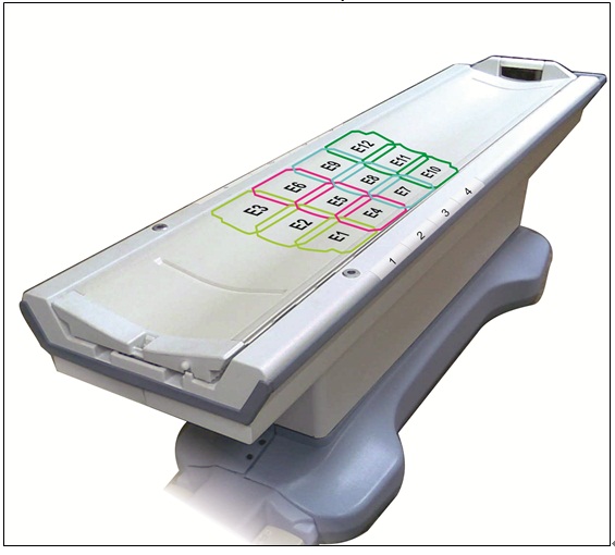
- The element layout for the PA coil is shown in Figure 19 below:
Figure 19. Element layout for PA Coil
4 Finalization
Finalization
No finalization steps.