1.5T Express Coil: 16E Head Neck Array Coil Cable Replacement
Prerequisites
Follow this process to change the system cable for coils that have a cable available as a spare part.
Procedure
- notice
- Unscrew the bottom cover and remove from coil. Retain the original screws used.
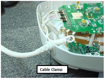
- Unscrew the cable clamp nut from the coil as shown in Figure 1.
Figure 1. Removing the Cable Clamp
- Identify the I board Assembly and the Coil ID PCB on the
Head Neck Unit HNU Only. See Figure 2.
Figure 2. Mux Board and Coil ID PCB Locations
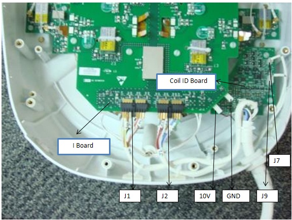
- Identify the RF GANGED Connectors (J1, J2) and DC Connectors Pins (10V and Gnd on I Board and J7, J9 on Coil ID Board). See Figure 2.
- Remove all RF connectors (J1, J2) from I Board. See Figure 2.
- Remove DC connectors: 10V and GND from I Board and J7, J9 from Coil ID PCB. See Figure 2.
- Remove the system cable (without the coil id).
- Install the new system cable.
- Align the cable into the notch of former slot.
- Connect RF connectors (J1 and J2) to Mux Board. Verify that all labels on the connectors match those on the I Board. See Figure 2.
- Connect DC connectors (10V & GND) to I Board and J7 and J9 to coil ID PCB. Verify that all labels on the connectors match those on the Mux Board and Coil ID Board. See Illustration 2.
- Replace cover. Use original screws to fasten cover.
 |
Finalization
Perform a MCQA Test.