1.5T 12-Channel Body Array Coil Cable Replacement
Prerequisites
1 Cable Removal
Procedure
- Put an ESD wrist strap on and ensure it is grounded.
- Place posterior coil patient side down.
- Remove the straps.
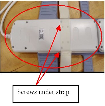
- Remove the 8 screws from the cover at the pelvic end of the
coil. There are two screws located under the strap. See Figure 1.
Figure 1. Back of Posterior
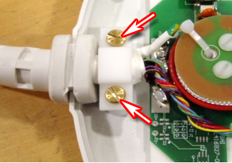
- Unscrew the cable clamp. See Figure 2.
Figure 2. Screws at Cable Clamp
- Locate and disconnect all RF cables coming from the cable trap.
See Figure 3.
Figure 3. Disconnect Indicated RF Cables
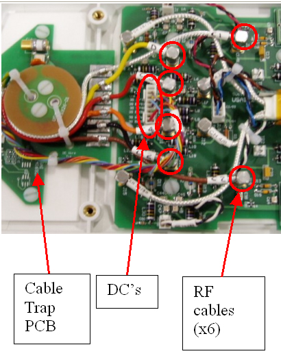
- Locate and remove the DC wire bundle coming from the cable trap. See Figure 3.
- Remove the two screws holding the cable trap PCB to the coil. See Figure 3.
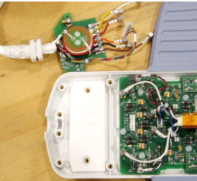
- Remove the cable from the coil. See Figure 4.
Figure 4. Posterior Cable Removal from Coil
2 Cable Replacement
Procedure
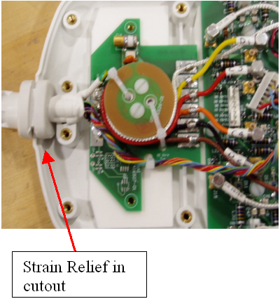
- Place strain relief in cutout (see Figure 5).
Figure 5. Strain Relief in Cutout
- Align cable trap PCB from the new cable with the screw posts.
- Secure the cable trap PCB in place with the previously removed nylon screws.
- Secure cable clamp over cable until tight with the previously
removed brass screws. See Figure 6.
Figure 6. Secured Cable Clamp
- Attach the DC wire bundle to J1. See Figure 7.
Figure 7. DC Wire to J1
- Attach the Clear cable at E1 Out.
- Attach the Yellow cable to E5 Out.
- Attach the Red cable to E3 Out.
- Attach the Orange cable to E4 Out.
- Attach the Black cable to E6 Out.
- Attach the Brown cable to E2 Out.
- Replace the cover.
3 Finalization
Finalization
If available, perform Multi-Coil Quality Assurance (MCQA) Tool to ensure that the coil still operates properly, otherwise perform the Surface Coils SNR Test.