1.5T 12-Channel Body Array Coil Troubleshooting
1 Personnel Requirements
2 Overview
The following tips can be used to troubleshoot common problems with the 12-Channel Body Array Coil for the MR450/MR450w P-connector and the single and dual connector coil for the HDx or HDxt system.
Legacy coils are shipped with coil-specific phantoms and positioners. New coils do not ship with phantoms. Phantoms and positioners come in a unified phantom set with the MR system.
3 Preliminary Requirements
3.1 Tools and Test Equipment
3.2 Replacement Parts
Some tests may require FRUs as listed in this section for diagnosis.
3.3 Required Conditions
The 1.5T 12-Channel Body Array Coil must be installed on the HDx, HDxt, MR450, or MR450w system.
-
GE_HDx BodyUpper
-
GE_HDx BodyLower
-
GE_HDx BodyFull
4 Procedure
4.1 Receiving No Signal
Problem:
Unable to prescan, or scanning but receiving no signal.
Possible Solution:
-
Verify that the port used to plug in the coil has a green light illuminated or a green lock indicated (port P1, P2 or P3, P4). This indicates the coil is properly plugged into the system.
-
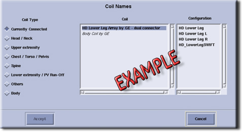
Verify that the system has correctly detected the coil by checking in the Currently Connected window in the GUI to select coils in Rx as shown below.
Figure 1. Currently Connected Coils Window on Scan Screen
-
Verify that the scan locations and any FOV offsets are correct.
-
Perform a continuity check on the output cable (Output Cable Check). This must be performed by a GE-authorized Service Engineer.
-
Verify that the coil is positioned with the cable exiting toward the bore.
-
Verify that the cable is not looped or crossed.
A problem can also exist at the system interface port. Try swapping both the connectors in the A and B ports. If still unable to get a signal, try to scan (transmit and receive) with the body coil. For this test, be sure to remove the imaging coil from the magnet bore before scanning with the body coil.
-
If still receiving no signal, the problem probably lies with the MR system.
-
If the scan completes successfully, there could be a problem with the coil. Contact GE for further assistance. If unable to scan with the substitute coil, there may be a system problem related to this particular coil type.
4.2 Image Quality
Problem:
Poor image quality, shaded images, or MCQA fails.
Possible Solution:
-
Perform a continuity check on the output cable (Output Cable Check). This must be performed by a GE-authorized Service Engineer.
-
Verify that there are no loops in the cables.
-
Verify that there are no metal or ferromagnetic objects close to the coil, patient or magnet (such as a safety pin or hair pin).
-
Verify that the coil is properly positioned.
-
Verify that the center frequency is within the frequency adjustment range for the system.
-
Verify that the R1, R2 and TG values from the prescan are within normally expected ranges.
If not already done, perform the coil MCQA Test. If the values obtained do not fall within normal operating parameters, investigate further by performing a phantom scan with the body coil. For this test, be sure to remove the imaging coil from the magnet bore before scanning with the body coil. If the problem persists, there could be an MR system problem.
-
If the body coil scan is satisfactory, acquire a scan using another coil of the same type (receive-only, phased array).
-
If the image quality is visibly improved, there may be a problem with the coil. Contact GE for further assistance.
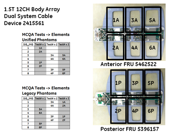
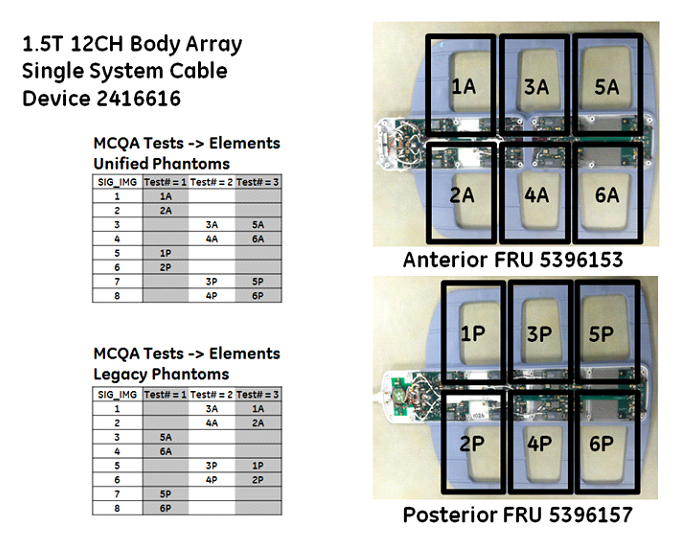
4.2.1 Coil Mapping Information
4.2.2 Example Results of MCQA on 1.5T 8-Channel Body Array Coil
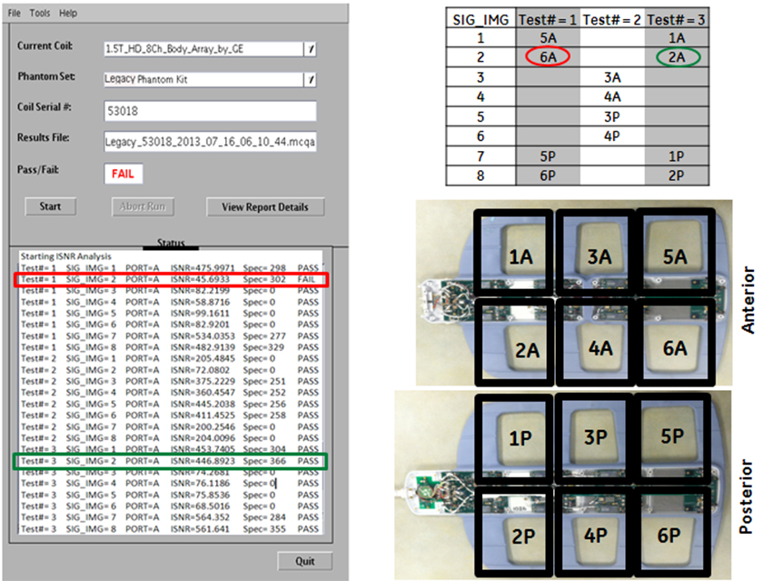
Example:
-
In this example, Test 1, Image 2 fails SNR.
-
This image 2 corresponds to the anterior element 6A.
-
Test 2 passes all images, however, does not test element 6A.
-
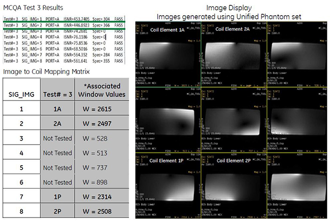
Test 3, Image 2 passes, but now it is testing anterior element 2A.
Conclusion: Receive chain from coil to recon is good; however, element 6A on the anterior part of the coil is bad. Replace the anterior FRU.
To view signal images, use Image Display in a 3 X 3 matrix. This will show each of the intermediate images (1 through 8), plus the composite image as image 9.
-
Images from coil elements being tested should have significant higher W/L values than images from elements not being tested.
-
Images from coil elements being tested, but that have significantly lower W/L values, would be considered failing.
Figure 2. MCQA Test 1 Results
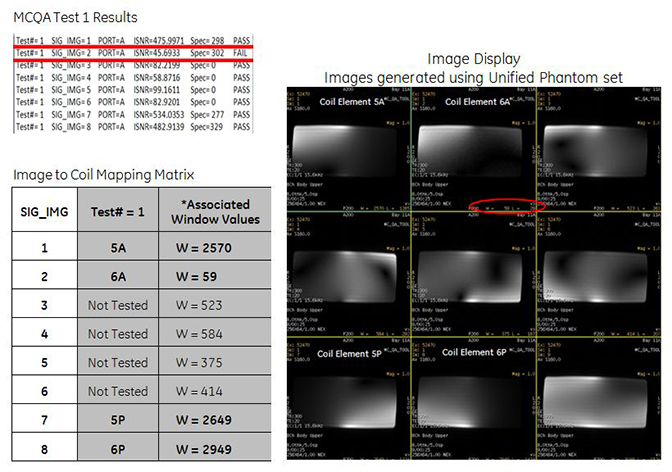
Figure 3. MCQA Test 2 Results
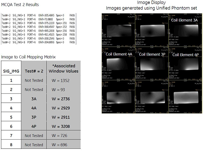
Figure 4. MCQA Test 3 Results
4.3 Artifacts
Problem:
Black line or signal void on the image.
Possible Solution:
Verify there is no metal present in the area being scanned in or on the patient.
4.4 Output Cable Check
4.4.1 Visual Check
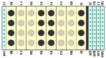
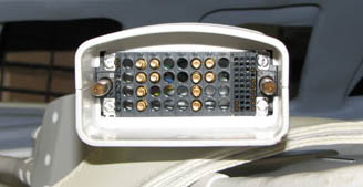
Before removing the cable assembly from the coil, visually inspect all coaxial connectors and pins on the coil connector. The figure below shows the pin layout of the single coil connector for an HDx or HDxt system. If there are any broken, deformed or recessed pins or coaxial connectors, replace the cable assembly.
|
There are two connectors in the dual connector coils.
Figure 5. Pin Layouts of Hypertronics Connector
4.4.2 Check for Continuity of DC Lines in External Cable (for HD Connector Coil)
-
Remove the cable assembly from the coil. Refer to Cable Replacement.
-
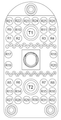
Use a digital volt meter (DVM) to check the resistance between the pin in the different columns and the corresponding DC wire. The table below shows these pins and corresponding DC wires. The resistance should be 0.2 ±0.2 Ohm. Use Figure 6 as a reference. If any resistance reading is not within this range, perform a Cable Replacement.
-
Check if any pin in the table above is shorted to ground. The outside conductor of a coaxial connector in column C, D, G, or H can be used as ground. If any pin is shorted to ground, perform Cable Replacement.
Figure 6. 12-Channel HD Connector
4.4.3 Check for Continuity in RF Cables from System Connector to Anterior Connector and System Connector to Posterior (for Coil with P-Connector)
-
Remove the cable assembly from the posterior and unplug the P-connector from the anterior. Refer to Cable Replacement.
-
Use a DVM to ensure an open circuit condition exists between the system connector and posterior coil-side RF cables. (See Figure 7 and Table 2.) Similarly, ensure an open-circuit condition between the system connector and the anterior P-Connector. (See Figure 8 and Table 3.) Use Figure 9 as a pin layout reference for the P-connector.
-
If the test fails, perform Cable Replacement.
-
Check for continuity in DC cables from the system connector to anterior connector and system connector to posterior.
-
Figure 7. Coil-Side RF Cables for Posterior Section
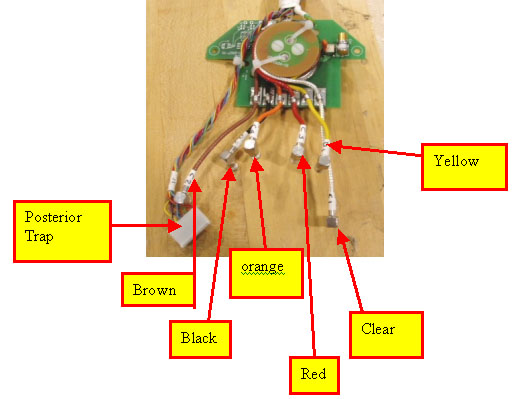
Figure 8. Anterior P-Connector RF Allocation
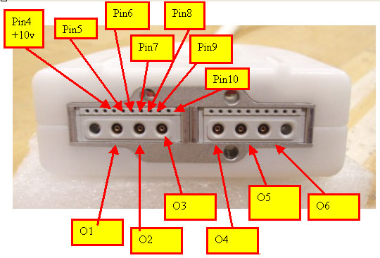
Figure 9. Pin Layout of P-Connector
-
Measure the open circuit condition P-connector and P-connector DC pins or between Hypertronics connector and P-connector DC pins. (See Table 4.) Use Figure 9 as a pin layout reference for the P-connector.
-
If the test fails, perform Cable Replacement.
-
Measure the open circuit condition between P-connector and 8-pin header or between Hypertronics connector and 8-pin header. (See the table below.)
-
If the test fails, replace the cable.
4.4.4 Check for Resistance in DC Cables from System Connector to Anterior Connector and System Connector to Posterior
-
Measure resistance using a DVM between the system connector pins and P-connector DC pins. See the table below, columns 3 and 4.
-
Measure resistance between the system connector DC pins and posterior 8-pin header. See the table below, columns 1 and 2. The resistance between the pins should be ≤2.7Ω.
-
If the resistance measured does not pass specification, perform Cable Replacement.