
- 00000018WIA30021F20GYZ
- id_131071213.3
- Apr 23, 2020 7:32:57 PM
T/R Quad Extremity Coil Replacements
Prerequisites
| Required persons | Preliminary requirements | Procedure | Finalization |
|---|---|---|---|
| 1 | Not Applicable | 30 minutes | Not Applicable |
| Item | Quantity | Effectivity | Part number | Manufacturer |
|---|---|---|---|---|
| Flat-head Screwdriver for No. 6 size screws | 1 | Cable Replacement | - | - |
| Flat-head Screwdriver for No. 4, 6 and 10 size screws | 1 | Mechanical Components | - | - |
| Digital Multimeter | 1 | Testing Cable Functionality | - | - |
| Loctite® 222 (12-month shelf life) | One 10 cc bottle | - |
46-170683P1 | - |
About this task
Follow this procedure to replace field replaceable units on the T/R Knee/Foot Coil by Invivo.
Cable Functionality
Cable Continuity Check
Procedure
Select the Ohmmeter function on the Digital Multi-Meter (DMM).Notice 
Figure 1. HD System Connector (View from Cable End) 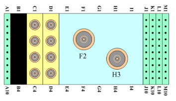
Cable Replacement
Procedure
Remove the bottom screws from the extended housing.Notice Figure 2. Cable Replacement 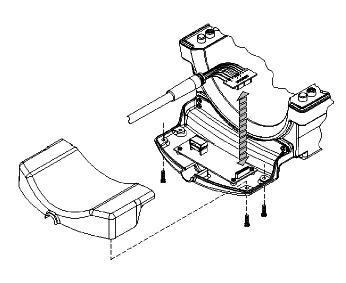
Mechanical Parts Replacement
Mechanical Hardware Check
Procedure
Draw Latch Replacement
Procedure
- Remove the two 6-32 x 0.438 FHMS brass screws from the housing, and replace the draw latch with the new one.
- Use Loctite 222 on the brass screws, insert them into draw latch and hand tighten.
- Test the draw latch to ensure proper assembly.
Handle and Cover – Coil Lock Replacement
Procedure
- Mate the new handle and cover pieces together, and fasten with the 4-40 x 0.375 PHMS brass screws.
- With both handle locks in the upright position, pry one side of the handle lock from the cradle on the side of the housing, and slide the lock assembly from the T-Bracket.
- Use Loctite 222 on the brass screws, replace the lock assembly with the new one, and secure with the screws.
- Place one end of the lock assembly into the cradle of the housing, and maneuver the other side into the cradle.
- Test the lock mechanism to ensure proper assembly.
T-Bracket Replacement
Baseplate Rail Replacement
Procedure
- Remove the four skid pads from the No. 6 PHMS screws and discard.
- Remove the No. 6 PHMS screws from the defective baseplate rail.
- Use Loctite 222 on the PHMS screws, replace the baseplate rail with the new one, and secure with the screws.
- Cover the No. 6 PHMS screws with the new skid pads from the kit.
What to do next
Finalization
No finalization steps.