- 00000018WIA30548E20GYZ
- id_131065274.0
- Feb 21, 2021 9:03:46 PM
HOShim Reference Map Creation and Verification
Prerequisites
| Personnel requirements | |||
|---|---|---|---|
| Required persons | Preliminary requirements | Procedure | Finalization |
| 1 | - | 60 minutes | - |
| Tools and test equipment | |||
|---|---|---|---|
| Item | Quantity | Part number | Manufacturer |
| LVShim Phantom Assembly | 1 | - | - |
| LVShim Phantom Inner Sphere | 1 | 2274476 | - |
| LV Phantom Small Half Assembly | 1 | 2306642 | - |
| LV Phantom Big Half Assembly | 1 | 2306645 | - |
| Required conditions |
|---|
| DQA calibration, Grafidy, LVShim, RF output adjustment, and UPM calibration (head and body) must be completed before running this procedure. |
| Software must be fully operational. |
| Gradient calibration must be within specification. |
| No image artifacts can be present. |
| ||||||||
About this task
High Order Shim (HOShim) Reference Map Creation uses the same phantom setup and protocol as LVShim.
Field Map Creation
Procedure
Set up and align the LVShim phantom.Notice Note:For DV systems earlier than 22.x, 1.5T uses green phantoms and 3.0T uses pink phantoms.
For DV systems 23.x and later, 1.5T uses green phantoms and 3.0T uses either green or pink phantoms.
Figure 1. Placing LVShim Phantom on Patient Table 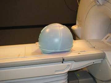
- Verify that the phantom is centered in the Z axis:
- Select the Grid Symbol button to turn
on the grid.
Figure 2. Centering LV Phantom (Alignment Grid) 
- Select the Grid Symbol button to turn
on the grid.
Running Makereference Script
About this task
On TRM systems, this section will take 45 minutes to complete. On the 3T/94 CRM, this section will take 90 minutes to complete.
Procedure
- Start the HOShim Reference Map tool:
The HOS Tool interface displays.
Figure 3. HOS Tool 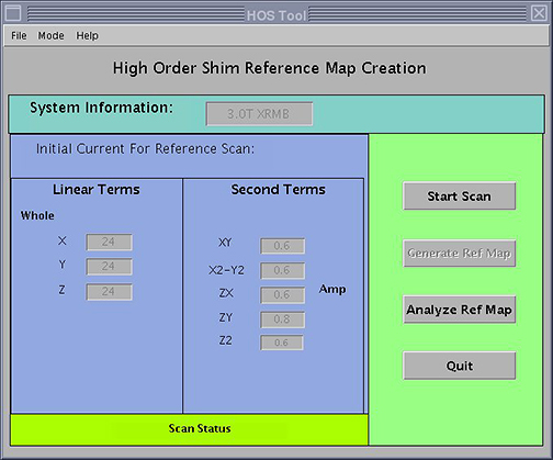
Calibration Verification
Procedure
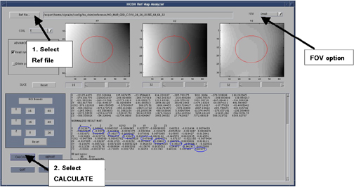
- If the FOV is 24 cm or 28 cm, set FOV to SMALL. If the FOV is 48, set FOV to LARGE.
Figure 4. HOSM Ref Map Analyzer