If not already done, disconnect the ECG cables from the PAC
and from each other.
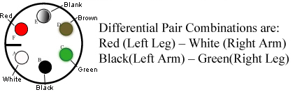
Figure 1. PIN Diagram of ECG Lead
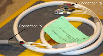
Check the impedance of the ECG cables from each of the leads at point A to the other end of that lead at point B. The impedance should be 60k ohms ±5% tolerance.
Figure 2. Connections A and B on ECG Cables
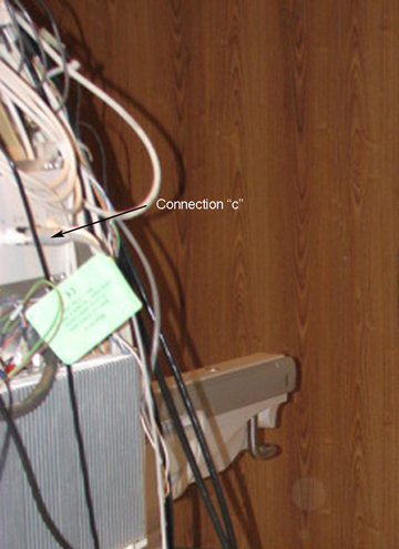
Check the impedance of the ECG cables from each lead at point B to its respective connection at point C. The impedance should be 0 ohms.
Figure 3. PAC Assembly with ECG Loads Connected
Connect Leads and Plug ECG Leads to PAC
Procedure
Connect the white high impedance MRI ECG lead wires to the gray
ECG patient cable by matching the colors on the white cable to the
colored dots on the gray cable.
Plug the open end of the gray ECG patient cable into the ECG port of the PAC. (See Figure 3.)