
- 00000018WIA300EFD20GYZ
- id_131070893.0
- Aug 29, 2019 1:57:06 AM
1.5T Phased Array Shoulder Coil Cable Replacement
Prerequisites
| Required persons | Preliminary requirements | Procedure | Finalization |
|---|---|---|---|
| 1 | Not Applicable | 30 minutes | Not Applicable |
| Item | Quantity | Effectivity | Part number | Manufacturer |
|---|---|---|---|---|
| Flat-blade Screwdriver | 1 | - | - | - |
| Item | Quantity | Effectivity | Part number | Manufacturer |
|---|---|---|---|---|
| 1.5T HD Shoulder Cable (DVw) | 1 | Coil P/N 5344905 |
5344456 |
SFO, India |
Procedure
- Remove the cover from the shoulder coil as shown.
Figure 1. Shoulder Coil with Cover Removed (P/N 5344905) 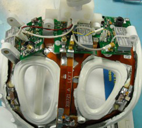
- Remove the two screws (shown below) that hold the cable clamp
in position. (Cable is captured beneath.)
Figure 2. Cable Clamp Screws (P/N 5344905) 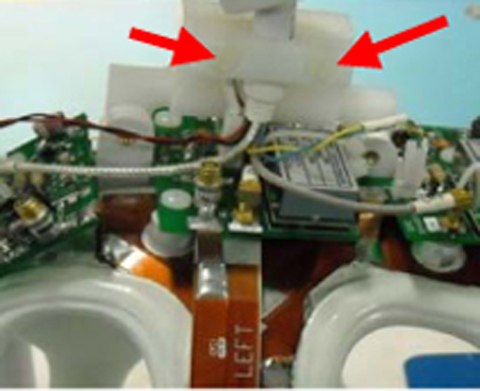
- Install the covers and replace the screws removed earlier. Make
sure to capture the strain relief inside of the covers.
Figure 3. Coil Cover Reinstalled 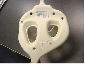
Finalization
No finalization steps.