Follow this process to change the system cable for coils that
have a cable available as a spare part. This process will be the
same whether replacing the coil or the cable.
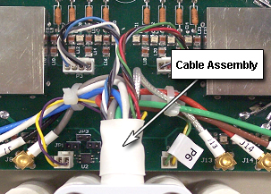
Attach the new cable assembly by sliding the strain relief of
the cable into the cutout of the housing, with its round section towards
the bottom. Press the strain relief down firmly, so the edge of the
housing fits into the groove of stain relief nicely.
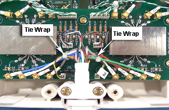
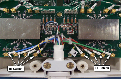
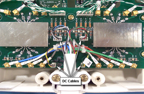
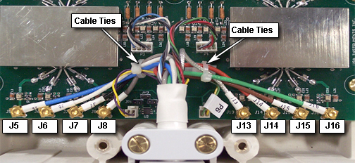
Install all channel connections (8 RF coaxial and 4 DC connectors)
by matching the designators on the cable with the designators on the
PCB. Tie cables J5, J6, J7, J8, and P5 to the left cable tie holder
on the PCB. Tie cables J13, J14, J15, J16, and P6 to the right cable
tie holder. Route the cables as shown in Figure 7, so no cables touch the rectangular shield. Cables
P3 and P4 should not be tied.
Figure 7. Installation of New Cable Assembly
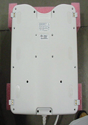
Install the coil cover by replacing and securing all screws
(total of 18). See Figure 1.
Finalization
Perform a system test to confirm that the repaired coil operates
properly.