
- 00000018WIA30F3FD20GYZ
- id_131058663.2
- Aug 26, 2020 3:21:37 AM
1.5T Split Top Head Coil SNR Test and Troubleshooting
| Required persons | Preliminary requirements | Procedure | Finalization |
|---|---|---|---|
| 1 | Not Applicable | 15 minutes | Not Applicable |
| Item | Quantity | Effectivity | Part number | Manufacturer |
|---|---|---|---|---|
| Head Loader Positioner | 1 | - |
5110241 | - |
| Head TLT Sphere with Loader | 1 | - |
2125244 | - |
| Curved Adapter Panel for Flat Table (GEM) | 1 | - |
5395828 | - |
| Condition | Reference | Effectivity |
|---|---|---|
|
The following coil configuration must be installed: HEAD. | - | - |
Follow this procedure to perform the Signal-to-Noise Ratio (SNR) test using the 1.5T Split Top Head Coil (P/N 5182594).
Position Coil and Phantom
The Quality Assurance (QA) check should be performed upon receipt of the coil to establish a baseline of coil performance. The procedure should be repeated at regular intervals. Use this procedure to position the Split Top Head Coil for a QA check.
-
Remove any other coil or unused accessory device from the magnet.CAUTION - Insert the Curved Adapter Panel Assembly into the magnet end of the table as shown.
Figure 1. Curved Adapter Panel Assembly 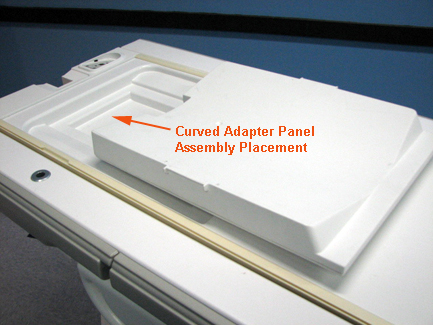
- Attach the head coil to the curved filler, and plug it into
P1 port on the LPCA:
- Make sure the cables extend into the magnet.
- Lock the baseplate into the table slots.
- Verify that the top and bottom sections of the head coil are properly aligned by making sure that the arrows on the Notice labels match as shown.
Figure 2. Aligning Top and Bottom Sections of Head Coil 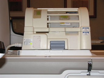 Note:
Note:The cables from the quick-disconnect box to the head coil should always be straight with no cross-overs or loops evident from the outside.
- Remove any pads from the coil.
- Slide the positioner and phantom onto the coil base as shown.
Figure 3. Positioner and Phantom in Head Coil 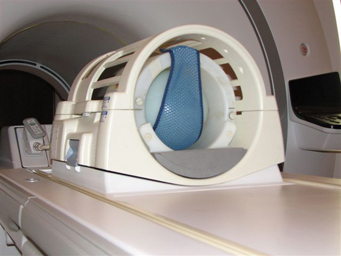
- At the magnet, press Alignment Light to turn on the lights.
- Move the cradle to align the coil with the alignment lights.
- Press Landmark to communicate the Region of Interest (ROI) center to the system.
- Press Move to Scan to move the coil into the scan position. Ensure the coil cable does not get snagged.
SNR Data Acquisition
- Create a new worklist item by clicking the icon shown.
Figure 4. Icon for New Worklist Item 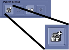
- Complete the Patient ID and Weight fields:
- Type geservice for the Patient ID.
- Type 111 lbs or 50 kg for Weight.
- Click the Show all Protocols button in the Exam section.
- Select Service from the Protocol library.
- Select snr check from the list in the left navigation pane, and click to open the folder.
- Select and move SNR Head Axial Scan to the right navigation pane, Multi-Protocol Basket.
- Click Accept.
- Click Start Exam.
- Click Save Rx.
- Click Scan.
- When the first scan completes, click Scan again. Select Same Series from the Scan Again pop-up that appears which asks where you want to add the images.
SNR Analysis Using NEMA Method
- Click the Service desktop icon.
- Click Service Browser to open it.
- Select the Utilities icon, then Image Quality-Nema.
- Select Click here to start this tool.
- In the mrt_nema window, type 1 for Signal To Noise Check and press Enter.
Figure 5. Starting SNR Check 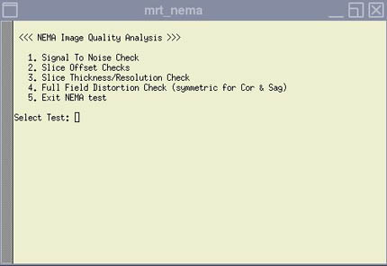
- Type x and press Enter to execute selected test.
- Type c for Select Images, press Enter, and type 2 and press Enter.
- Type x and press Enter to execute the selected test.
- Type 2 to accept the default and display the SNR results.
Figure 6. SNR Results 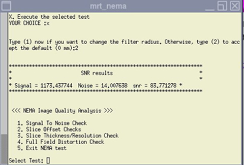
SNR Specifications
The SNR measurements must be greater than or equal to the specifications below.
| Coil | SNR |
| 1.5T Split Head Coil | 29.1 |
Troubleshooting
- External Cable Check: Do not check cable continuity at the connector as it may cause pin damage.
-
Mechanical Hardware Check:
- Check the ODU connector for mechanical damage, such as cracks.
- Inspect the contact pins on the ODU connector for damage from improper insertion or corrosion, etc.
- Make sure cradle latches and top latches are operating and still have adequate range of motion.
Finalization
No finalization steps.