
- 00000018WIA30D6DD20GYZ
- id_131063664.0
- Feb 3, 2021 2:45:20 AM
Coil Datapath Diagnostics for GEM (RRX)
Diagnostic Link
Diagnostics >> System Function >> RF >> Coil Datapath Diagnostics
Purpose
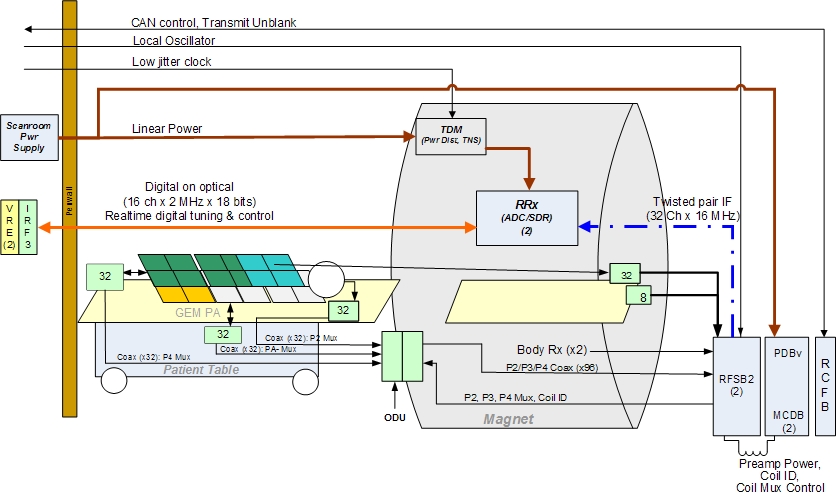
The coil datapath diagnostic (CDD) tests the signal paths between the coil connectors and the coil inputs to the RF hub. It also tests portions of the RF hub that are not covered by internal board level or datapath diagnostics. The test uses the MCRv tool.
There are 2 MCRv tools; one for 1.5T and another for 3.0T. The difference between the tools is the controller with oscillators for the different field strengths.
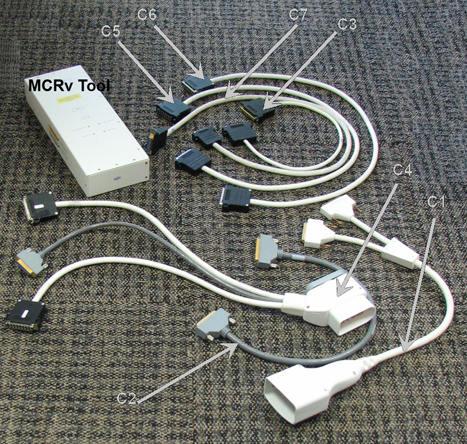
Physically, the MCRv tool is a hardware module that emulates a coil. This module must be connected to the coil inputs or to other points along the coil cable path before starting the diagnostic. The MCRv tool generates known test signals and provides known loads that the diagnostic can measure to verify the correct connectivity between the points where the tool is connected and the rest of the system. The MCRv tool is supplied with a variety of cables that allow you to attach the tool to various points along the receive path.
The ports where the MCRv tool can be connected are:
-
P1 and A connector in the LPCA
-
P2 and P4 in the table
-
PA-Mux under the left side table covers
-
RF switch board (RFSB2)
The tests are organized by coil connector type, starting with the pathways/connectors that are farthest away (the longest signal paths). There are 3 different paths by connector type shown in the columns of the table below. Note that the longest signal paths are at the top of the column. Typically, you want to start testing with the coil connector.
| Cable Description | Quant | Approx. Length | Easy Label |
| A-port adaptor | 1 | 600 mm (~23.6”) | C1 |
| 37-pin sub-D, Male-Fem | 1 | 600 mm (~23.6”) | C2 |
| 8w8, male-female | 1 | 600 mm (~23.6”) | C3 |
| P-port adaptor | 1 | 600 mm (~23.6”) | C4 |
| 25-pin sub-D, male-female | 1 | 1000 mm (~39.4”) | C5 |
| 16w16, male-female | 2 | 1000 mm (~39.4”) | C6 |
| 16w16, male-male | 2 | 1000 mm (~39.4”) | C7 |
Requirements
1.5T MCRv tool kit, part # 5182417
Test Sequence
-
Click on the Service Browser button on the Service Desktop Manager to launch the Common Service Desktop. Select the Diagnostics tab.
-
Under the Diagnostics tab, select System Function, RF, and Coil Data Path Diagnostics.
-
In the Coil Path to Test list, select a path.
-
In the MCRv Tool Connection Point list, choose a connection point.
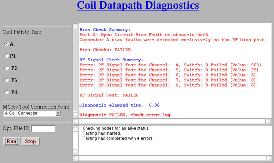
Figure 2. Coil Datapath Diagnostic 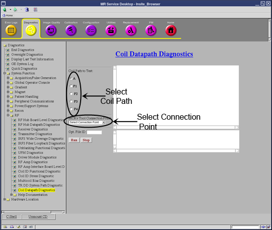
-
Physically connect the MCRv tool to the appropriate connection point.
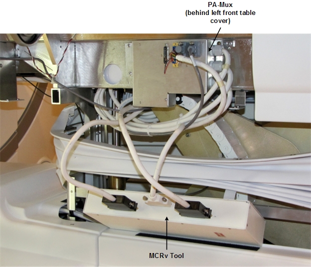
Figure 3. Port Locations 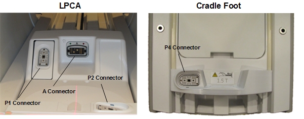
-
To specify a custom log filename, enter text in the Opt. File ID field.
-
Click Run.
P2 and P4 are connection sockets on top of the cradle. The PA-Mux multiplexer box is located behind the left side covers of the table (see Figure 7).
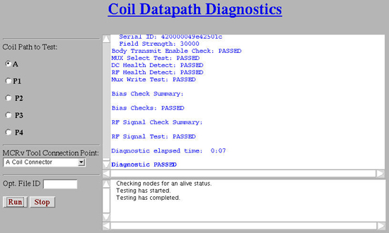
Expected Results
Test Setup Instructions and Troubleshooting
Use the table below for instructions on how to set up each test.
To validate the system, test each port, starting at A in the top row, and work from left to right. To troubleshoot, start in the column of the failing port and work down that column to resolve the failure.
| A | P1 | P2 (in Flat table) | P4 (in Flat table) | PA-Mux (in Flat table) |
| A Coil Connector — 'A' Coil Connector | P Coil Connector — 'P' Coil Connector | P Coil Connector — 'P' Coil Connector | P Coil Connector — 'P' Coil Connector | PA-Mux Interface – Flat (GEM) Table Only — PA-Mux Interface |
| A Cable Chain — 'A' Cable Chain | — | — | — | — |
| A Port RF Switch Board — 'A' RF Switch Board | P1 RF Switch Board — 'P1' RF Switch Board | P2 RF Switch Board — 'P2' RF Switch Board | P4 RF Switch Board — 'P4' RF Switch Board | PA-Mux RF Switch Board — 'PA-Mux' RF Switch Board |
Coil Connectors
There are five coil connectors. Two coil connectors are accessed through the LPCA: A and P1. In addition, P2, P4, and PA-Mux are on the table.
P2 and P4 are connection sockets on top of the cradle. The PA-Mux multiplexer box is located behind the left side covers of the table.
The coil connector test validates each connector separately by connecting the proper adaptor cable to the MCRv tool and running the indicated test below. The test validates both the signal (RF) path and the control (DC) path for that connector.
A Pass in the test means that all receive and control circuitry is OK and you can quit.
| Notice | |
|---|---|
Refer to the connection instructions below to run an associated test.
A Coil Connector
-
Attach one end of the C1 (A port adaptor cable) to the A connector.
-
Attach the other end to connectors J1 and J5 of the MCRv tool.
If the test fails, first check that the connections are firmly seated, ensure the screws are properly tightened, and then rerun the test. If the test fails again, consider running tests in A Cable Chain Interface - A Cable Chain Interface.
P Coil Connector
-
Attach one end of the C4 (P port adaptor cable) to the proper P connector.
-
Attach the other end to connectors J2, J3, and J4 of the MCRv tool. J3 is connected to 16W16 cable labeled RF channels 1-16 and J4 is connected to 16W16 cable labeled RF channels 17-32.
If a test fails for P1, P2, or P4, first check that the connections are firmly seated and ensure the screws are properly tightened. Rerun the test. If necessary, reseat the P1 connector (the P2 and P4 connectors cannot be reseated) and reseat all test cable connections. If the test continues to fail, consider running the tests in RF Switch (RFSB2) Board - ‘P’ RF Switch Board.
If a test fails for cables from the PA-Mux, first check that the connections are firmly seated and ensure the screws are properly tightened. Rerun the test. If necessary, reseat all test cable connections. If the test continues to fail, consider running tests located in PA-Mux Interface – Flat (GEM) Table Only - PA-Mux Interface.
PA-Mux Interface – Flat (GEM) Table Only
This diagnostic tests connectivity from the PA-Mux.
-
Remove the left side cover of the table (when viewing the table from the foot end) to access the PA-Mux.
-
Disconnect J3 from the PA-Mux and connect it to J2 of the MCRv tool.
-
Disconnect J1 from the PA-Mux and connect it to J3 of the MCRv tool.
-
Disconnect J2 from the PA-Mux and connect it to J4 of the MCRv tool.
A Cable Chain Interface
This diagnostic tests connectivity of the cable chain interface in the magnet bore.
A Cable Chain
-
Attach C2 (37-pin sub-D Male-Female) to J2 of A Cable Chain Panel (PED-LPCA) and to J1 of MCRv tool.
-
Attach C3 (8w8 Male-Female) to J1 of A Cable Chain Panel (PED-LPCA) and to J5 of MCRv tool.
Alternative Tests
If the previous test fails, first check that the connections are firmly seated and ensure the screws are properly tightened. Rerun the test. If necessary, reseat all test cable connections. If the test continues to fail, consider running tests located in RF Switch (RFSB2) Board - RF Switch Board.
RF Switch (RFSB2) Board
A Port RF Switch Board
-
Attach C2 (37-pin sub-D Male-Female) to RFCB J6 in Slot 11 to J1 of the MCRv tool.
-
Attach C3 (8w8 Male-Female) from RFSB2 A1/A2 in Slot 1 to J5 of the MCRv tool.
P1 RF Switch Board
-
Attach C5 (25-pin sub-D Male-Female) to RFCB J1 in Slot 11 to J2 of the MCRv tool.
-
Attach C7 (16w16 Male-Male) to P1 of the RFSB2 in Slot 1 and to J3 of the MCRv tool.
-
Attach C7 (16w16 Male-Male) to P1 of the RFSB2 in Slot 2 and to J4 of the MCRv tool.
P2 RF Switch Board
-
Attach C5 (25-pin sub-D Male-Female) to RFCB J2 in Slot 11 to J2 of the MCRv tool.
-
Attach C7 (16w16 Male-Male) to P2 of the RFSB2 in Slot 1 and to J3 of the MCRv tool.
-
Attach C7 (16w16 Male-Male) to P2 of the RFSB2 in Slot 2 and to J4 of the MCRv tool.
P4 RF Switch Board
-
Attach C5 (25-pin sub-D Male-Female) from RFCB J4 in Slot 11 to J2 of the MCRv tool.
-
Attach C7 to MCRv tool J3. The connection to the RFSB2 and the associated connector number is dependent on channel number selected and is displayed in a popup window when the channel number is selected.
PA-Mux RF Switch Board
-
Attach C5 (25-pin sub-D Male-Female) from RFCB J3 in Slot 11 to J2 of the MCRv tool.
-
Attach C7 to the MCRv tool J3. The connection to the RFSB2 and the associated connector number is dependent on channel number selected. This information is displayed in a popup window when the channel number is selected.
Depending on which parts of the diagnostic fail, the RFSB2, the MCDB, the RF hub backplane (unlikely), or something upstream could be defective. Run additional RF hub diagnostics and/or swap RFSB2 or MCDB boards to help isolate bias failures to the switch board or driver board.