
- 00000018WIA3042FD20GYZ
- id_131066323.0
- Aug 29, 2019 1:57:13 AM
1.5T 8ch Breast Array Coil P Port FRUs and Replacement
1.5T Breast Array Coil FRU
| Item | Description | GE Part Number |
| 1 | FRU, 1.5T Breast Coil | 5404748 |
| 2 | FRU, 1.5T Kizuna Breast Cable | 5721429 |
| 3 | Breast Coil Small Parts Kit FRU | 5404927 |
| 4 | FRU, 1.5T Kizuna Breast Coil Positioner | 5554683 |
| 5 | Phantom Positioner, Breast | 5343432 |
| 6 | FRU, HEADREST, GEM BREAST COIL, FLAT TABLE | 5416939 |
| 7 | FRU, BIOPSY MECHANISM ASSEMBLY | 5416940 |
| 8 | BREAST COIL PAD KIT GEM | 5409517 |
Breast Coil Positioner Installation
Follow this procedure to install the Breast Coil Positioners. The coil positioners are required to be installed prior to turning the coil over to the customer. Prior to returning the FRU through the service process the coil positioners are required to be removed from the coil. The part will not fit in the coil packaging.
Personnel Requirements
| Required Persons | Procedure Timing |
| 1 | 10 minutes |
Preliminary Requirements
Tools and Test Equipment
| Item | Qty |
| Standard Tool Set (P/N 5112581) | 1 |
Parts
| Item | FRU Part Number | Qty | |
| Phantom Positioner, Breast | See FRU List | 1 | |
Procedure
-
Position the coil to expose the bottom cover and screws.
Figure 1. Bottom Cover and Screws 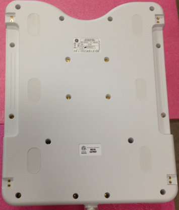
-
Install two breast coil positioner using the screws that ship with the coil or FRU.
Figure 2. Bottom Cover and Screws 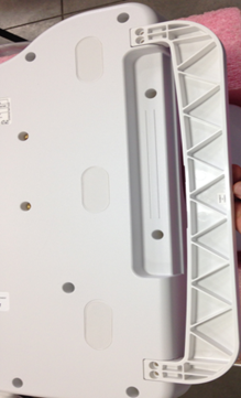
Breast Cable Replacement
Follow this procedure to replace the system cable on the Breast Coil Before beginning this procedure, remove the coil from the magnet room. Wear an ESD wrist strap to avoid electrostatic discharge.
Personnel Requirements
| Required Persons | Procedure Timing |
| 1 | 45 minutes |
Preliminary Requirements
Tools and Test Equipment
| Item | Qty |
| Standard Tool Set (P/N 5112581) | 1 |
| ESD Wrist Strap | 1 |
Parts
| Item | FRU Part Number | Qty | |
| 1.5T Breast Coil System Cable | See FRU List | 1 | |
Procedure
-
Position the coil to expose the bottom cover and screws
Figure 3. Bottom Cover and Screws -
Remove all screws (18).
-
Remove the cable from the coil.
-
Remove the 2 cable ties.
Figure 4. Cable Connections 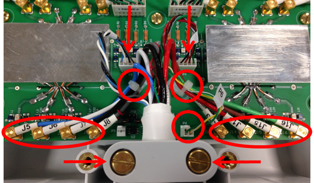
-
Disconnect all 8 RF cables and 3 DC cables
-
Remove cable clamp from the coil.
-
Remove cable assembly.
-
-
Install the new cable:
-
Attach the new cable assembly by sliding the strain relief of the cable into the cutout of the housing, with its round section towards the bottom. Press the strain relief down firmly, so the edge of the housing fits into the groove of stain relief nicely.
-
Reinstall the cable clamp.
-
Install all channel connections (8 coaxial and 3 DC connectors) by matching the designators on the cable with the designators on the PCB. Tie cables J5, J6, J7 and J8 to the left cable tie holder on the PCB. Tie cables J13, J14, J15, J16, and P6 to the right cable tie holder. Route the cables as shown in the picture, so none of them touches the rectangular shield. Cables P3 and P4 should not be tied.
Table 2. Connection RF Wires Color Label Blue J5 White J6 Black J7 Gray J8 Clear J13 Red J14 Brown J15 Green J16 DC Wires Gray, Black, White and Blue (Twisted) P3 Green, Brown, Red and Black/White (Twisted) P4 Yellow/White and Green/White (Twisted) P6
-
-
Secure the cover to the coil with the screws removed in step one.
Finalization
Run the MCQA Tool to verify the Breast Coil operates properly.