
- Optima MR450w BASE 1.5T System Service Methods
- 5690012-2EN Revision 3
- 00000018WIA3047AE20GYZ
- id_131075383.0
- Aug 29, 2019 1:34:36 AM
Operator Display and Control Panels Replacement
Prerequisites
| Required persons | Preliminary requirements | Procedure | Finalization |
|---|---|---|---|
| 1 | 5 minutes | 45 minutes | 5 minutes |
| Item | Quantity | Effectivity | Part number | Manufacturer |
|---|---|---|---|---|
| Non-Magnetic Tool Kit | 1 | - |
5112581 | - |
| Item | Quantity | Effectivity | Part number | Manufacturer |
|---|---|---|---|---|
| In-Room Display (option) | 1 | - |
See FRU Manual | - |
| Trackball Control Panel (option) | 1 | - |
See FRU Manual | - |
| E-Stop Panel | 1 | - |
See FRU Manual | - |
| Push Button Control Panel (option) | 1 | - |
See FRU Manual | - |
| 7-Segment Display | 1 | - |
See FRU Manual | - |
| ||||
About this task
This document provides the procedures for replacing operator control/display hardware in the front magnet enclosure. This document covers both the in-room display (IRD) version and the version without the IRD.
Replacing In-Room Display
Procedure
- Note:Remove the laser light cover. It is held in place by two screws and a popper.
The PDU must be powered down completely to prevent damage to system electronics.
Figure 1. In-Room Display (IRD) 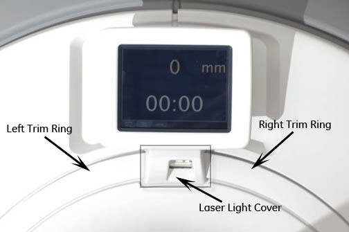
Figure 2. Removing Laser Light Cover 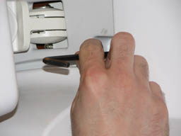
- Remove top panel on back of the IRD by popping tabs with a small
flat head screwdriver.
Figure 3. Removing IRD 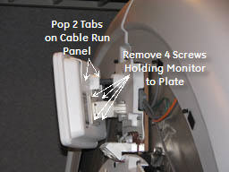
Replacing Trackball Control Panels and E-Stop Button
Procedure
- Note:Remove the front panels. See Front Cover Removal and Installation.
The PDU must be powered down completely to prevent damage to system electronics.
Figure 4. Removing Front Cover 
- Disconnect the two cables that connect the control panels to
the magnet enclosure.Note:
If cable connectors are not labeled with a J number, mark the applicable J number on each cable connector before removal.
Figure 5. Removing Control Panel Cables 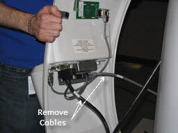
Remove the trackball control panel by removing five screws and detaching the emergency stop (e-stop) button cable.Warning Figure 6. Removing Trackball Control Panel 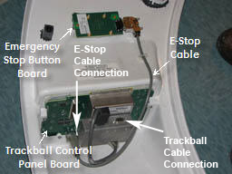 Note:
Note:If you are only replacing the e-stop button board, disconnect the e-stop cable and remove two screws. Install the new button.
Figure 7. Trackball Connector 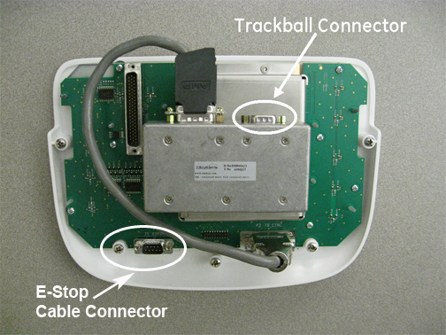
To install the new trackball control panel, follow Step 2 through Step 4 in reverse order.Notice Figure 8. EMO Reset on PDU 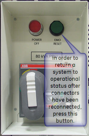
Replacing 7-Segment Display (7SD)
Procedure
- Remove the 7SD bezel. It is held in place by one screw and four
poppers.
Figure 9. 7SD 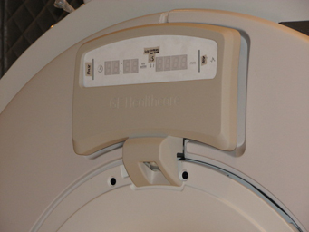
Figure 10. Removing 7SD Bezel 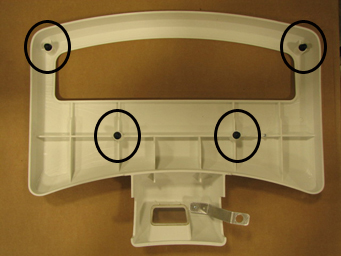
- Remove the four screws to remove the 7SD from the mounting bracket.
Figure 11. Removing 7SD 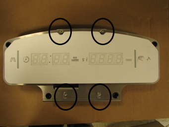
Replacing Push Button (Non-Trackball) Control Panel and E-Stop Button
Procedure
- Disconnect the cable that connects each control panel to the
magnet enclosure.
Figure 12. Removing Front Covers 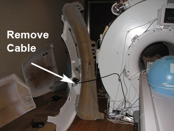 Note:
Note:If cable connectors are not labeled with a J number, mark the applicable J number on each cable connector before removal.
Figure 13. Removing Control Panel Cables 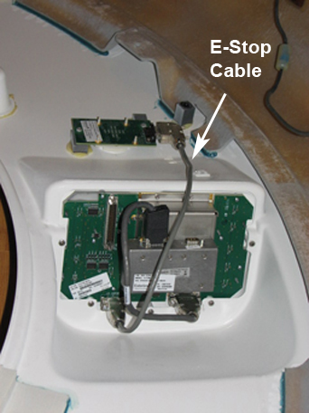
- To install the new 7SD control panel, follow Step 2 through Step 4 in reverse
order.
Figure 14. EMO Reset on PDU