
- Optima MR450w BASE 1.5T System Service Methods
- 5690012-2EN Revision 3
- 00000018WIA30C6AE20GYZ
- id_131075463.0
- Aug 29, 2019 1:34:43 AM
Front Cover Removal and Installation
Prerequisites
| Personnel requirements | |||
|---|---|---|---|
| Required persons | Preliminary requirements | Procedure | Finalization |
| 1 | - | 15 minutes for front cover; 30 minutes for GEM light strips | 15 minutes |
| Tools and test equipment | |||
|---|---|---|---|
| Item | Quantity | Part number | Manufacturer |
| Pair: Cut-Resistant Gloves | 1 | - | - |
| Nonmagnetic Titanium Service Tool Kit, Large Set | 1 | 5112581 | - |
| EPX Plus II Applicator | 1 | 5265376 | - |
| Mixing Nozzle, 3M Scotch-Weld EPX Applicator, 50 ml, PN 62-9154-9148-4 or Equivalent | 1 | 46-252065P154 | - |
| Consumables | |||
|---|---|---|---|
| Item | Quantity | Part number | Manufacturer |
| Plexus MA300 Adhesive, 50 ml | 1 | 5774729 | - |
| Adhesive Cable Tie Mount | 1 | 46-208747P1 | - |
| DV Light Assembly | 1 | 5766238 | - |
| 5.6 inch Cable Tie | 1 | 46-208758P2 | - |
| Replacement parts | |||
|---|---|---|---|
| Item | Quantity | Part number | Manufacturer |
| Front Cover | 2 | See FRU manual | - |
| ||||
About this task
Overview
This document contains the procedures for front cover removal and installation. The front covers consist of two halves and contain the emergency stop and control panels for the system.
Preliminary
Procedure
- Turn off and perform LOTO on the RF and PEN cabinets. See the MR Service Safety Manual, PN 5452735.
- Undock the patient table and position the table away from the magnet.
Front Cover Removal
About this task
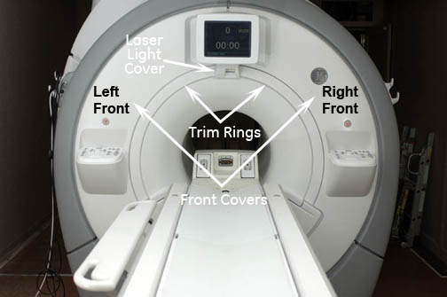
Procedure
- For an in-room display (IRD) system:
- Remove the alignment laser light cover by unscrewing the two
screws. The cover is held in place by a popper on the lower left corner.
Figure 2. Removing the Laser Light Cover 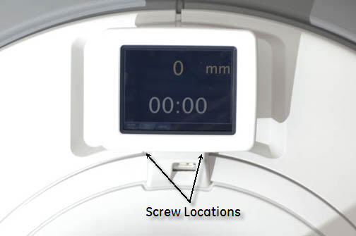
- Remove the two trim rings by pulling away from the enclosure.
They are held in place by four poppers on each side.
Figure 3. Removing the Trim Ring 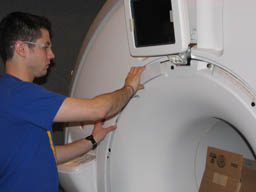
- Remove the alignment laser light cover by unscrewing the two
screws. The cover is held in place by a popper on the lower left corner.
- For a 7-segment display (7SD) system:
- Remove the right trim ring.
Figure 4. 7-Segment Display Bezel 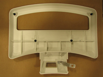
- Remove the right trim ring.
- For both systems, remove the two M6 screws that secure the front
bridge cover.
Figure 5. Front Bridge Cover Screws 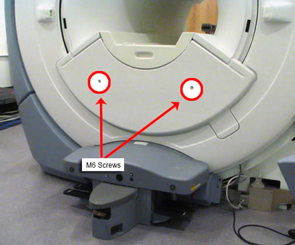
Figure 6. Front Bridge Cover Removed 
- Remove the front cover(s) by unscrewing the seven screws on
the left-hand front cover and the six screws on the right-hand front
cover. Unscrew the two additional screws shared by both sides. There
are fifteen screws total.Note:
Be careful of the operator control panel connection cables.
Figure 7. Unbolting Front Cover 
- To free each front cover, disconnect the cables that connect
the control panel to the magnet Replacing Operator Display and Control Panels and disconnect the room ambient temperature sensor cable from the
left front cover Room Ambient and Bore Temperature Sensor
Replacement.
Figure 8. Left Front Cover 
Vertical Light Strip Replacement
About this task
For left or right light strip removal, remove the corresponding side middle and side front covers.
Procedure
- Disconnect the power cord from the corresponding light strip.
Figure 9. Disconnect the light strip power cord 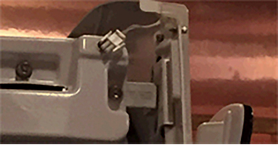
- Remove the translucent light cover.
Figure 10. Remove the translucent light cover 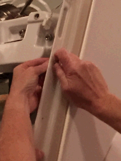
- Remove the clips holding the lights to the cover. Cut the wire ties on the back side holding the light strip wire and remove the light strip.
Figure 11. Remove the clips 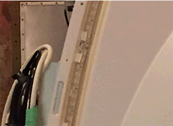
Figure 12. Cut the wire tie holding the strip wire  Note: If the current LEDs in the cover are already mounted to adhesive mounts, proceed to Step 10.
 - CAUTION: Nitrile gloves must be worn when using alcohol wipes and glue.Assemble the glue gun applicator using the 1:1 plunger, following the manufacturer's instructions included in the box. Make sure to connect the glue and mixing nozzle to the applicator assembly.
Figure 13. Glue gun with 1:1 plunger 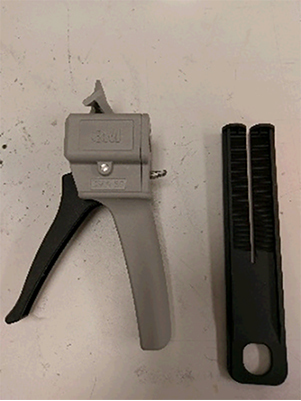
Figure 14. Assembled glue gun 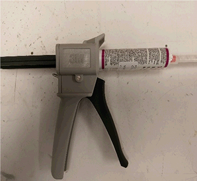
- Clean the location where the adhesive mounts will be installed using the alcohol wipes provided in the FRU kit.
Figure 15. Clean the LED groove 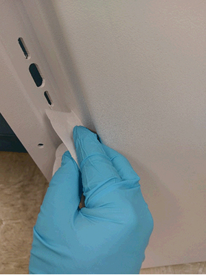
- Install the adhesive mounts into the LED groove. Make sure to install one at the top and one at the bottom of the cover, with the remaining 9 spaced approximately 200 mm apart in the LED groove. Placement is not critical, but should span the whole groove.
Figure 16. Adhesive mount installation and placement 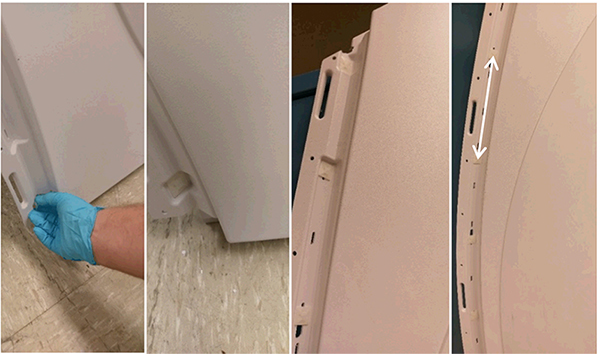
- Using the gun applicator, liberally apply glue to the vertical sides of the adhesive mounts. Wait until the glue is no longer tacky (approximately 10 minutes) before continuing to the next step.Note: It is critical that glue coverage does not extend outside of the LED groove, and that glue does not interfere with the slots for cable tie installation.
Figure 17. Glue application 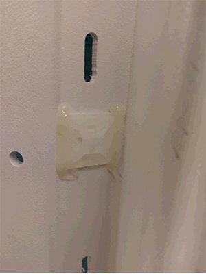
- Install the LED strip starting from the bottom to the top of the panel, pealing the backing off the LED strip (approximately 12 inches) to expose the adhesive tape, and continuing up the side as the LED strip is placed. Between adhesive mounts, make sure to press the LED onto the cover to eliminate any gaps.
Figure 18. LED installation 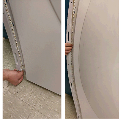
- Loop the cable ties through the adhesive mounts, locking the LEDs in place.
Figure 19. Cable tie installation 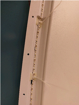
- Clip the excess from the cable ties.
Figure 20. Clip excess cable tie 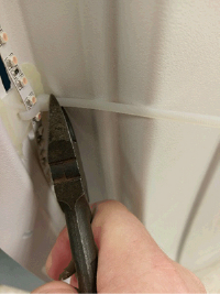
Figure 21. Proper LED placement 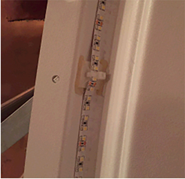
Finalization
Procedure
- For in room display (IRD) systems:
- Whenever the IRD or trackball control panels are disconnected and then reconnected, the host PC needs to be rebooted.
- After reboot, from the Common Service Desktop, select Diagnostics > Hardware Location > Magnet Room > In Room Display.
- The diagnostic displays the current status of the IRD and trackball connectivity. If the status is not installed, recheck connections, reboot, and check the In Room Display diagnostic again.
- For 7-segment display (7SD) systems, check the functionality of the item replaced. Run the associated diagnostic, if necessary. From the Common Service Desktop, select Diagnostics > Hardware Location > Magnet Room > SRI Functional Tests.