- Optima MR450w BASE 1.5T System Service Methods
- 5690012-2EN Revision 3
- 00000018WIA30208110GYZ
- id_20040806.9
- Apr 23, 2020 8:50:33 PM
Checking the ECG leads
Testing the electrical connections on the ECG cables
Prerequisites
| Personnel requirements | |||
|---|---|---|---|
| Required persons | Preliminary requirements | Procedure | Finalization |
| 1 | - | 5 minutes | - |
| Tools and Test Equipment | |||
|---|---|---|---|
| Description | Quantity | Part Number | Manufacture |
| Ohmmeter | 1 | - | - |
Procedure
- If not already done, disconnect the ECG cables from the PAC and from each other.
Figure 1. PIN Diagram of ECG Lead 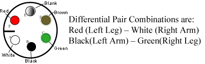
- Check the impedance of the ECG cables from each of the leads at point A to the other end of that lead at point B. The impedance should be 60k ohms ±5% tolerance.
Figure 2. Connections A and B on ECG Cables 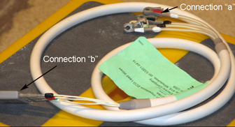
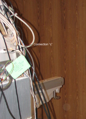
- Check the impedance of the ECG cables from each lead at point B to its respective connection at point C. The impedance should be 0 ohms.
Figure 3. PAC Assembly with ECG Loads Connected