- Optima MR450w BASE 1.5T System Service Methods
- 5690012-2EN Revision 3
- 00000018WIA30386C40GYZ
- id_20195532.3
- Feb 17, 2021 10:30:04 AM
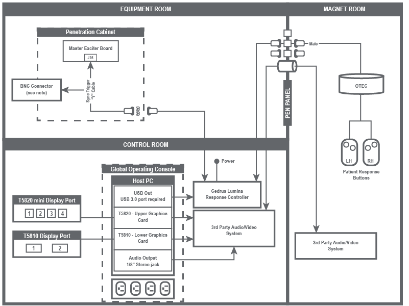
Installing BrainWave On Console hardware
Interconnect diagram
Note: If necessary, BrainWave components can obtain power from the outlets inside the GOC. To get access to the outlets, you must remove the right side of the GOC cover.
Note: Tape up the BNC connector from the Y-cable and leave it unplugged.
Note: The cable between Cedrus Lumina Response Controller and the PEN panel may be short. If it is too short, use the provided cable (5778183) as needed.