- Topic ID: id_17423016
- Version: 4.0
- Date: Apr 22, 2019 12:55:48 AM
Z-Alignment
Prerequisites
Overview
This document provides the necessary steps to align the X-Ray Tube with the Detector and Collimator in Z-axis direction.
1 Data Acquisition
Procedure
- Move table to longitudinal home position.
- Remove scan window.
- Select CALIBRATION from Service Desktop.
- Select Z ALIGN.
- If Attention window is displayed when tool
is launched, CAREFULLY READ and click ACCEPT.note:
Tube Install Certification service procedure will need to be performed as part of the Cold Iso Alignment Finalization section.
note:If CANCEL is clicked, the tool is dismissed.
- Once the ACCEPT button is clicked, another Attention window will be displayed. CAREFULLY READ and click OK.
- Click MOVE.
- Verify DESIRED TUBE POSITION in Tube Position window is 0.
- Click OK in Tube Position window if CURRENT TUBE POSITION is not 0.
- Click DISMISS in Tube Position window.
- Click SCAN.
- Press START on SCIM when it flashes.note:
If one or more tube spits occur, repeat steps 11 and 12.
- Click CALCULATE.
- If no adjustments are required, click DISMISS and skip to section 5.note:
If “Z-Axis Tube Alignment PASSES Specification” and “Detector Skew FAILS Specification”, check collimator and detector functionality, perform appropriate corrective action, and retest.
2 Mechanical Alignment
Procedure
- Remove right side gantry cover.
- Stop the rotor of X-ray tube in case of Liquid Bearing Tube before HVDC off. Refer to Liquid Bearing Tube Rotor stop procedure for details.
- Turn off HVDC ENABLE, AXIAL DRIVE ENABLE and 120 VAC ENABLE switches on Service Switch panel.
- Remove scan window, gantry left side cover, gantry top covers
and gantry front cover.note:
Gantry front-cover control panels and display functionality are required during this procedure.
- Manually rotate gantry until X-Ray tube reaches 2 o'clock position.
- Engage rotational lock.
- Mount dial indicator gauge on Z-Axis mounting bracket, located
on tube assembly front face, with gauge's probe resting perpendicular
to tube casting's front face (Item 1 in Figure 1).
Figure 1. Dial Indicator Mounting and Adjustment Screws Locations
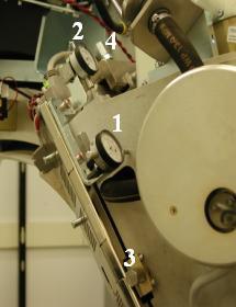
- Mount dial indicator gauge on X-Axis mounting bracket, located on tube assembly left face, with gauge's probe resting perpendicular to tube casting's left face (Item 2 Figure 1)
- Set both dial indicators to zero.
- Loosen four M12 mounting bolts on tube assembly about 1/4 to 1/2 turns with a 10mm hex bit socket drive and 12 inch extension.
- Turn Z-axis adjustment screw, located on tube assembly front
face, in direction specified by Z-Align tool, until dial indicator
shows Z-Align calculated value (Item 3 in Figure 1).
EXAMPLE: “Z-Align Adjust 5.000 mm 200.000 mils (move towards gantry).”
note:1 mil is equal to 0.001 inches.
note:Turn adjustment screw counterclockwise for “move towards gantry.” Turn adjustment screw clockwise for “move away from gantry.”
- Tighten four M12 mounting bolts on tube assembly in a cross
pattern configuration, with a 10mm hex bit socket torque wrench and
12 inch extension, to the following torque values:note:
Ensure that neither dial indicator values change during tightening step.
- Disengage rotational lock.
- Turn on 120 VAC ENABLE, AXIAL DRIVE ENABLE and HVDC ENABLE switches on Service Switch panel.
- Press ESTOP RESET on Service Switch panel and wait until scan hardware is reset.
- Click RESTART from Z-Align tool and repeat Section 4.1, Steps 4 - 11 until no adjustments are required.