- Topic ID: task_pvv_2hw_1jb
- Version: 2.0
- Date: Oct 28, 2019 4:24:35 AM
Shorted Inverter Test
Prerequisites
Overview
Objective: The purpose of this test is to verify that the HV power inverter is working properly. The inverter is commanded at a fixed frequency and is loaded with a short circuit. Verification is made that the inverter currents are correctly set. At the same time verification is made that no High voltage is measured. This test is performed without connecting the HV Tank to the inverter so that no X-ray is generated. Anode rotation and filament drive are not activated during this test. This test requires manual operation.
-
Summary:
-
Disconnect HV Tank from Inverter
-
Short Inverter HV output
-
Run Diagnostic
-
Reconnect HV Cable from Inverter to Tank
Procedure
 warning
- Stop the rotor of X-ray tube in case of Liquid Bearing Tube before HVDC off. Refer to Liquid Bearing Tube Rotor stop procedure for details.
- Remove Service Switch Panel (SSP) cover from the gantry rear cover.
- Turn OFF the 120VAC, Axial Drive and HVDC switches on the gantry’s Service Switch Panel.note: Always turn OFF HVDC before 120VAC. Turning OFF 120VAC power before HVDC power can result in equipment damage.
- Remove gantry side and front covers.Refer to Parts Replacement > Gantry > Enclosure > (Cover Removal Procedures).
- Disconnect the HV Tank primary cables from the inverter. Take care not to disconnect at the same time the plate cable connected to the quad snubber board which is tightened with the HV Tank primary cables.
- Install the short circuit cable (2404798–2) included in the first aid spare. See Figure 1.
Figure 1. Short Circuit Cable
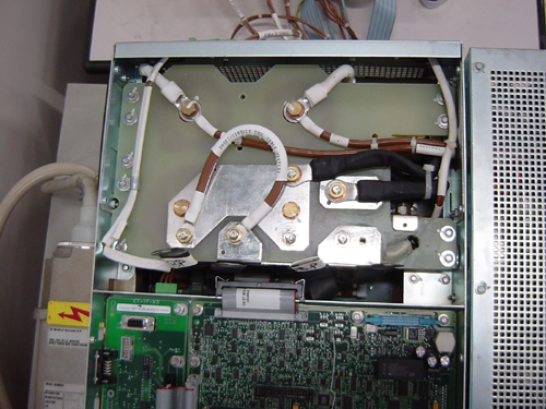
- The parallel inductor and serial inductor must be connected.
- Tighten the Azimuth lock pin.
- Restore power to the gantry.
- Enable the 120VAC and HVDC using the Service Switch Panel. Press ESTOP DRIVES RESET also.
- Verify that the DS1-DS2 leds on inverter quad snubbers board is lit.
- Verify that the DS300 neon on inverter gate_cmd board is lit.
- Launch the GENERATOR TOOL.
- Launch the SHORTED INVERTER DIAGNOSTIC tool.
- Run the diagnostic. Verify:
-
No error is reported on the console.
-
After "exposure", no error is reported.
-
- Remove power to the gantry using proper lockout / tagout procedure.
- Remove the short circuit cable, reconnect the HV Tank primary cables.
Finalization
- If this test fails, and the “Inverter Gate Command Test” passed, your system probably has an inverter problem.
- Refer to the following troubleshooting:
- Note 1: Ilp and Ilr currents not detected.
- Check the -15V (Led DS2) on PPC kV control board (see block diagram).
If it is not lit, refer to “other failures” section. Else:
- Power off the Generator. Wait until all neons are off.
- Check that the currents transformers (capacitor set) to gate_cmd board cable is correctly connected. If yes:
- Check that the inverter inductors are correctly connected. If yes:
- Check that HV Tank is correctly connected to the capacitors set. If yes:
- Check that the gate_cmd to HV Tank cable and HV Tank to PPC kV control cables are correctly connected.
If yes, replace the inverter.
- Reconnect all the cables.
- Note 2: Ilp current not detected.
- Power off the Generator. Wait until all neons are off.
- Check that the parallel inductor is correctly connected. If yes:
- Check that the parallel inductor impedance is 0 Ohms. If no: replace inverter. If yes:
- Check that inverter capacitors (capacitors set) are not broken. If yes, replace the capacitor set. Else:
- Disconnect the currents transformers to gate_cmd board cable. Check that the parallel current transformer impedance is 0. If no: replace the capacitor set. Else:
- Check that the gate_cmd to HV Tank cable and HV Tank to PPC kV control cables are correctly connected. If yes:
- Disconnect the HV Tank to PPC kV control cable. Check that the impedance between pin20 and pin21 of J2 of HV Tank is 3,3Ohms. If no replace the inverter. If yes: replace PPC kV control board.
- Reconnect all the cables.
- Note 3: Ilr current not detected.
- Power off the Generator. Wait until all neons are off.
- Check that the inductors are correctly connected. If yes:
- Disconnect the currents transformers to gate_cmd board cable. Check that the serial current transformer impedance is 0. If no: replace capacitor set. Else:
- Check that inverter capacitors (capacitors set) are not broken. If yes, replace the capacitor set. Else:
- Check that the gate_cmd to HV Tank cable and HV Tank to PPC kV control cables are correctly connected. If yes:
- Disconnect the HV Tank to PPC kV control cable. Check that the impedance between pin20 and pin21 of J2 of HV Tank is 5 Ohms. If no replace inverter. If yes: replace PPC kV control board.
- Reconnect all the cables.
- Note 4: Ilr current resonant frequency is lower than expected.
- Power off the Generator. Wait until all neon’s are off.
- Check that the inductors are correctly connected. If yes:
- Check that inverter capacitors (capacitors set) are not broken. If yes: replace the capacitor set. Else:
- Disconnect the currents transformers to gate_cmd board cable. Check that the parallel current transformer impedance is 0. If no: replace the capacitor set. Else: replace PPC kV control board.
- Reconnect all the cables.