- Topic ID: id_17423035
- Version: 4.0
- Date: Jan 20, 2020 8:32:53 PM
Power Cable (CFHC - Heater Routing Assembly and Fuse Board)
Prerequisites
Overview
This procedure defines the necessary steps to Remove and Install the Power Cable (CFHC ↔ Heater Routing Assembly and Fuse Board).
1 Preparation
Procedure
- Move table to home position, fully out and down.
- Remove right side gantry cover.
Refer to Parts Replacement → Gantry → Enclosure → (Cover Removal Procedure).
- Stop the rotor of X-ray tube in case of Liquid Bearing Tube before HVDC off. Refer to Liquid Bearing Tube Rotor stop procedure for details.
- Turn OFF the Axial Drive and HVDC switches on the gantry’s Service Switch Panel.
- Position the detector at 12 o'clock and lock gantry rotation.
- Turn OFF the 120 VAC switch on the gantry’s Service Switch Panel.
- Remove the gantry left side cover, top covers and front cover.
2 Replacement Procedure
Procedure
- Cut tie-wraps holding the cable to DAS assembly.
- Disconnect all cable connectors of the power cable, and remove the cable.
- Put the new power cable into place, and connect all cable connectors of it.
- notice
- Secure the power cable using tie-wraps.
Figure 1. Power Cable Wiring
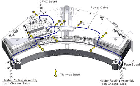
- Rotate the gantry by hand to ensure there is no interference between the power cable and stationary components.
 |
3 Gantry Reassembly
Procedure
- Make sure the Axial Drive, HVDC and 120 VAC switches on the gantry’s Service Switch Panel are OFF.
- Release the gantry rotational lock and install gantry covers,
all except the right side cover.
Refer to Replacement → Gantry → Enclosure → (Cover Removal Procedures).
- Turn on the 120 VAC, HVDC and Axial drive service switches.
- Install gantry right side cover.
4 Finalization
Procedure
- Perform a [Quality Assurance Test] from the [Functional Checks] menu of the service manual to ensure system operation.