- Topic ID: id_17423045
- Version: 3.0
- Date: Apr 22, 2019 12:56:38 AM
Gantry Stationary (CFC) Fan Control Module Replacement
Prerequisites
Overview
This procedure defines the steps necessary to replace the stationary side Fan Control Module.
1 CFC Module Removal
Procedure
- Remove gantry right side cover.
Refer to
- Stop the rotor of X-ray tube in case of Liquid Bearing Tube before HVDC off. Refer to Liquid Bearing Tube Rotor stop procedure for details.
- Turn OFF the Axial Drive, HVDC and 120 VAC switches on the gantry’s Service Switch Panel.
- Remove the gantry left side cover.
- Perform all required LOTO activities to ensure no power to the gantry.
- The CFC module is located on the left side of the gantry. See Figure 1.
Figure 1. CFC Module
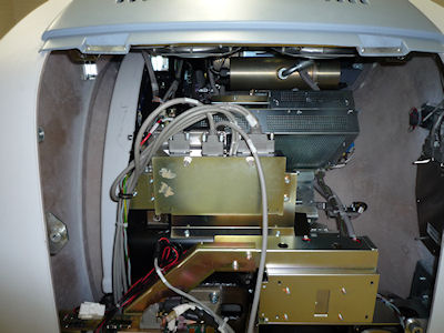
- The CFC module has 4 cables on the top. Disconnect all 4 cables before removing the module.
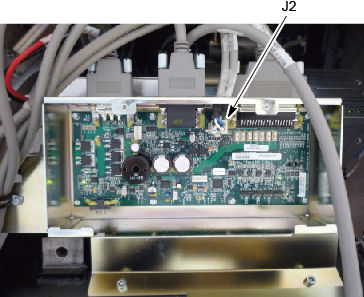
- Using the 2 thumbscrews, open the cover on the CFC module.
- Inside, remove the Molex connector from J2.
Figure 2. J2 Connector
- The CFC board is secured to housing with 8 hex-head screws. Remove all screws with a hex wrench.
- Remove the CFC board.
2 CFC Module Replacement
Procedure
- Install the new CFC board using the 8 screws.
- Reconnect all cabling removed, reference section above.
- Install CFC front cover after installing the molex internal connection.
- Remove the LOTO and power up the system.
- Enable 120 VAC HVDC and Axial Drive service switches from the
service switch panel. Press the table drives enable button on the
lower right corner of the service switch panel.
Check to make sure all top cover fans come on right after gantry power up and that the gantry blower fan on the lower left comes on. Fans come on at 50% during hardware reset process.
- Install the gantry left and right side covers.
3 Finalization
Procedure
- Monitor the operator message area until the system indicates the detector temperature has returned to normal.
- Perform a Fastcal from the Daily Prep button on the Operator console.
- Perform a Quality Assurance Test from the Functional Checks menu of the service manual to ensure system operation.