- Topic ID: id_16157523
- Version: 5.0
- Date: Jan 23, 2022 10:51:49 PM
Gantry Bore Cover Removal and Re-Install
Prerequisites
Overview
This procedure explains how to remove and re-install the CT Gantry rear cover.
1 Removal
Procedure
 danger
- Stop the rotor of X-ray tube in case of Liquid Bearing Tube before HVDC off. Refer to Liquid Bearing Tube Rotor stop procedure for details.
- notice
- Remove gantry side covers, top covers and Mylar window. Refer to each cover’s removal procedure.
- Remove gantry rear cover and move away from the gantry. Refer to Gantry Rear Cover Removal procedure.
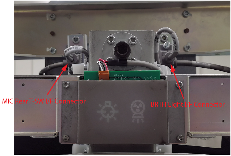
- Disconnect BRTH Light I/F cable and MIC REAR T-SW I/F cable
from the top of the bore cover.
Figure 1. BRTH Light and MIC REAR T-SW I/F Cable Connnectors
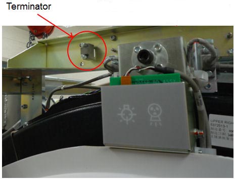
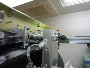
- Connect the terminator to MIC REAR T-SW I/F connector.
Figure 2. Terminal Position
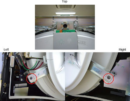
- Remove the 2 screws located at two bottom brackets of the bore
cover. Then loosen the screw on top. Refer to .Figure 3
Figure 3. Screws of Bore Cover
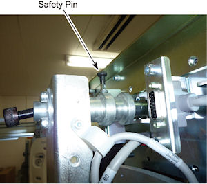
- Pull up safety pin small knob on the bore cover top bracket
and rotate 1/4 turn to keep the safety pin disengaged.
Figure 4. Safety Pin
- caution
- With two persons, pull out the bore cover from the gantry stationary brackets and place it on the floor.
 |
 |
2 Installation
Procedure
- caution
- With two persons, lift the bore cover and attach it to the gantry
stationary brackets. Insert the top of the cover bracket to the gantry
stationary bracket first.
Figure 5. Bore Cover Attachment
- Tighten 3 screws located at top and two bottom brackets of the cover.
- Remove the terminator from the MIC REAR T-SW I/F connector and restore it to the original location.
- Connect the BRTH Light I/F cable and MIC REAR T-SW I/F cable to the connectors.
|
3 Finalization
Procedure
- Continue with other cover installation procedures as necessary. When AC power is restored to the system, prior to enabling axial drive or HVDC, remember to rotate the gantry by hand to ensure there is no interference between covers and rotating components.
- Verify all covers, especially side covers are properly secured.
- Ensure there is no interference during all tilt range.