- Topic ID: task_lkm_lb5_2jb
- Version: 5.0
- Date: May 20, 2022 6:18:18 AM
Collimator Primary Aperture Replacement
Prerequisites
Overview
This procedure documents how to remove and replace the collimator primary aperture.
1 Procedure
Procedure
- Position the table to its lowest position if not already done.
- Stop the rotor of X-ray tube in case of Liquid Bearing Tube before HVDC off. Refer to Liquid Bearing Tube Rotor stop procedure for details.
- Remove the gantry right side cover.
- Turn off the three (3) main power switches (Axial Drive, HVDC and 120VAC) on the Service Switch Panel. Power down the console and perform LOTO procedures to lock out power on the gantry.note: Always turn OFF HVDC before 120VAC. Turning OFF 120VAC power before HVDC power can result in equipment damage.
- To aid in access to the Collimator, remove the gantry left side cover, top covers, front cover and rear cover.
- Rotate the Gantry until the Tube reaches the 3 o'clock position.
- Remove the Tube by following the procedure in X-Ray Tube Replacement.
- Remove the CCB chassis cover from the Collimator Assy by loosening four fasteners.
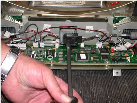
- Using a straight slot screwdriver, drive the collimator filters to the home position. See Figure 1. This reduces the chance of contamination and potential image quality problems.
Figure 1. Collimator Filter
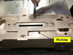
- Before removing the interposer plate, outline its position with a marker as shown in Figure 2. This facilitates returning the collimator to its original position later. Do NOT use pencil to make your mark as pencil lead is conductive.
Figure 2. Mark Interposer Plate Position (example)
- Remove the defective Primary Aperture from the Collimator.
Figure 3. Collimator Primary Aperture Removal
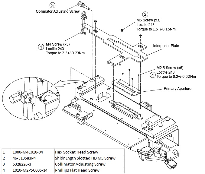
- Remove three (3) M4 screws from the interposer plate, see Figure 3 → item 1.
- Remove three (3) M5 screws from the interposer plate, see Figure 3 → item 2.
- After removing the interposer plate screws, unscrew the collimator adjusting screw until the plate can be removed, see Figure 3 → item 3.
- Remove six (6) M2.5 flat screws from the defective Primary Aperture, see Figure 3 → item 4.
- With a flat blade screwdriver, carefully pry out the Primary Aperture.
- Clean any debris away from the Collimator.
- Install the new Primary Aperture in reverse order, clean the underside of any debris.
- Apply correct Loctite and torque information for all screws, refer to Figure 3.note: Re-attach the Interposer Plate, re-aligning it to the previously marked position. See Figure 2.
- Reinstall the CCB chassis cover to the Collimator Assy.
- Reinstall the Tube by following the procedure in X-Ray Tube Replacement.
- Remove LOTO and install all of the gantry covers except the gantry right side cover.
- Enable 120VAC, HVDC and Axial Drive service switches panel. Press the table drives enable button on the lower right corner of the service switch panel.
- Install the gantry right side cover.
2 Finalization
No finalization steps.