- Topic ID: id_17423028
- Version: 3.0
- Date: Apr 22, 2019 12:56:30 AM
CFHC Replacement
Prerequisites
Overview
This document provides the necessary steps to replace and configure the Common Fan and Heater Controller Assembly (CFHC) for imaging.
1 CFHC Assembly Removal
Procedure
- Move table to home position.
- Remove gantry right side cover.
- Stop the rotor of X-ray tube in case of Liquid Bearing Tube before HVDC off. Refer to Liquid Bearing Tube Rotor stop procedure for details.
- Turn off [HVDC ENABLE], [AXIAL DRIVE ENABLE] and [120 VAC ENABLE] switches on Service Switch panel.
- Remove power to system. See Equipment Service - Lockout-Tagout-PPE from Safety section.
- Remove gantry left side cover and gantry top covers, and slide the gantry front cover.
- Rotate gantry such that CFHC assembly is in 2 o'clock position.
- Engage rotational lock. See Equipment Service - Lockout-Tagout-PPE from Safety section.
- Disconnect four cables and two power cables from CFHC Assembly.
- Move cable bundle away from CFHC Assembly in order to avoid damage during CFHC Assembly removal / install process.
- Remove four screws, and remove CFHC Assembly from gantry.
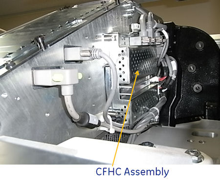
Figure 1. CFHC Assembly Mounting
2 CFHC Assembly Installation
Procedure
- Position CFHC Assembly on to gantry and fasten with four screws.note:
when cable is connected, be careful NOT to cover the exit window.
- Connect four cables and two power cables to CFHC Assembly.
- Disengage rotational lock. See Equipment Service - Lockout-Tagout-PPE from Safety section.
- Restore power to system. See Equipment Service - Lockout-Tagout-PPE from Safety section.
- Turn on 120 VAC ENABLE, AXIAL DRIVE ENABLE, and HVDC ENABLE switches on Service Switch Panel.
- Press ESTOP RESET on Service Switch panel and wait until scan hardware is reset.
3 Setup, Checks, Alignments, and Calibrations
Procedure
- Gantry Rotation Safety Check
- Gantry Balance Procedure
- Turn off [HVDC ENABLE], [AXIAL DRIVE ENABLE] and [120 VAC ENABLE] switches on Service Switch panel.
- Install gantry front cover, gantry top covers, gantry left side cover and scan window.
- Turn on 120 VAC ENABLE, AXIAL DRIVE ENABLE, and HVDC ENABLE switches on Service Switch Panel.
- Press ESTOP RESET on Service Switch panel and wait until scan hardware is reset.
- Install gantry right side cover.