- Topic ID: task_sl2_ytd_wjb
- Version: 2.0
- Date: Dec 10, 2019 2:30:43 AM
Belt Removal and Installation
Prerequisites
Overview
1 Drive Belt Removal
Procedure
- Remove the gantry covers (see gantry cover replacement procedures if needed) and slipring cover.
- Stop the rotor of X-ray tube in case of Liquid Bearing Tube before HVDC off. Refer to Liquid Bearing Tube Rotor stop procedure for details.

 danger

- notice
- Turn off the three (3) main power switches (Axial Drive, HVDC, 120VAC) on the gantry’s Service Switch Panel. Remove all system power at the Main Disconnect panel and use proper Lockout/Tagout procedures.
- Remove the Home Flag assembly to prevent damage.
Refer to the Home Flag and Sensor Board Assembly Replacement procedure in the menu of this publication, for details.
- Remove the Axial Encoder to prevent damage to the encoder gear teeth.
Refer to the Axial Encoder Assembly Replacement procedure menu of this publication, for details.
- Using the 5mm hex key remove the three (3) screws that secure the Drive Gear Cover, and remove the Cover.
- Rotate the tube to the 1:00 position. Do not engage the rotational lock.
- Loosen the two (2) M12 screws with the 10mm hex key.
Refer to Section 2, step3 in Axial Drive Assembly Replacement procedure, for details.
- Using the 6mm hex key and the 12 inch extension, fully loosen the elongated hex screw to remove the drive belt from the drive gear.
See Figure 6 in Axial Drive Assembly Replacement, for details.
- Remove the drive belt from the drive gear.
- Work the belt toward the table on the rotating assembly. Keep all slack at the tube side of the gantry.
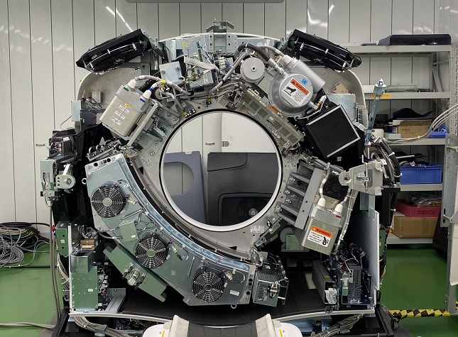
- Work the belt through the large gap, around the inverter and to the DAS (see Figure 1).
Figure 1. Tube Position
- At this point the Belt slackens. Carefully work the belt around the rest of the rotating gantry, completing the removal process.
2 Drive Belt Installation
Procedure
- Install the Belt using the removal steps, 10 through 12, in reverse order.
- Install the Home Flag and Axial Encoder.
- Slide the Belt over the main Drive Gear and align it towards the back of the rotating assembly teeth. Check both top and bottom.
- Work the belt through the pulley tensioner assembly and place on motor drive gear.
- Tighten the elongated hex screw using a 6mm hex key and a 12 inch extension. Apply enough tension so the washer can be rotated with your fingers.
- Rotate the Gantry by hand several times and recheck tension of washer. Make sure the belt does not slip off tensioning pulley and is tracking correctly toward the rear of the gantry.
- Repeat step 5 and 6 as needed until the correct tension is achieved (when the washer can be turned by finger with some difficulty).
- Tighten the two (2) M12 screws using a 10mm hex key to 50 Ft-lbs (66.4 N-m). This locks the tensioner assembly.
3 Finalization
Procedure
- Ensure that the Home Flag Assembly and the Axial Encoder Assembly have been installed and are functioning correctly.
Refer to the Home Flag and Sensor Board Assembly and Axial Encoder Assembly Replacement procedures, in the menu of this publication.