- Topic ID: task_bmc_pgd_wjb
- Version: 2.0
- Date: Dec 10, 2019 2:30:23 AM
Axial Drive KIM Board Replacement
Prerequisites
Overview
This procedure describes the steps necessary to install a new KIM board into the Titan axial drive assembly. The KIM board is an interface board to match the system control signals to the new drive type.
1 Preparation for Replacement
Procedure
- notice
- Stop the rotor of X-ray tube in case of Liquid Bearing Tube before HVDC off. Refer to Liquid Bearing Tube Rotor stop procedure for details.
- Remove gantry right side cover and disable Axial drive, HVDC and 120VAC service switches from the service switch panel.
Refer to Replacement > Gantry > Enclosure > (Cover Removal Procedures).
- Remove the gantry left side, top and front covers. Connect the cover E-stop circuit to the terminators on the gantry.
- Disconnect KIM com and TGPG cables from KIM board. Refer to Figure 1.
Figure 1. KIM Com and TGPG Cable Connections
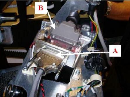
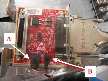
- Disconnect axial drive cable and power supply cable from KIM board. Refer to Figure 2.
Figure 2. KIM to Axial Drive Cable and KIM to Power Supply Cable
- Remove Velcro strap holding wires in place at the back of the assembly. This strap is connected to the KIM bracket, which will be removed with removal of the KIM assembly in the next step.
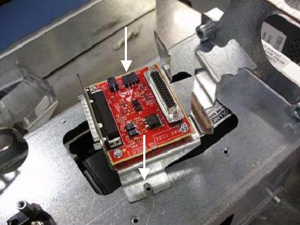
- Remove existing KIM board assembly from axial drive assembly using a 3mm hex wrench. Refer to Figure 3. Removing the entire assembly allows for easier access when replacing the KIM board itself.
Figure 3. Mounting of KIM board assembly to axial drive assembly
- Remove the plastic cover from the KIM board bracket by flexing the plastic. Keep the cover to replace it after the new KIM board is in place.
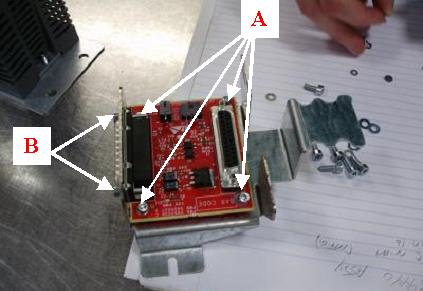
- Remove the four (4) M3 screws and small screws on the board to remove the KIM board from the bracket. Refer to Figure 4. Keep the screws to use in the replacement of the new KIM board.
 |
2 Installing KIM Board on Assembly Frame
Procedure
- Mount the new KIM board to bracket with four (4) M3 screws and flat washers with a 2.5mm hex wrench. Refer to Figure 4.
- Use small screws from old KIM assembly to attach new assembly to bracket.
Figure 4. Mounting of KIM Board onto bracket
- Mount bracket onto axial drive assembly with two (2) M4 screws, lock washers and flat washers using a 3mm hex wrench. Refer to Figure 3.
- Mount plastic cover to top of assembly, flexing cover to fit in bracket slots. Refer to Figure 5 for any questions regarding mounting procedure.
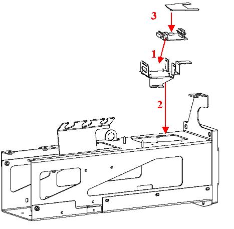
Figure 5. Illustration of steps for KIM Board Replacement
3 Cable Installation and Routing
Procedure
- Connect the wire from the X1 port of the axial drive to the larger port on the side of the KIM board. Refer to Figure 2.
- Connect red and black cables from the power supply into the smaller KIM board port. Refer to Figure 2.
- Connect the KIM com cable into the KIM board assembly. Refer to Figure 1.note: Make sure the two boxed ends of KIM com cable are inserted into the X7 and X8 ports of axial drive. The pins are positioned so that the end will only go in one way. Also make sure the remaining end of the cable is connected into the X12 port of the axial drive.
- Connect the TGPG cable into the top back side of the KIM board assembly. Refer to Figure 1.
4 Reassemble gantry
Procedure
- Install the gantry front cover, top and left side covers.
- Turn on the Axial drive, HVDC and 120VAC services switches from the service switch panel.
- Install the gantry right side cover.
5 Finalization
Procedure
- Run the System Scanning Testfrom the Functional Checks procedure list.
- Plug in any options the customer has to the interface panels as applicable for your site. Perform any defined functional checks for the options plugged into the interface panels.