- Topic ID: task_drl_brc_wjb
- Version: 2.0
- Date: Dec 10, 2019 2:30:24 AM
Axial Drive Brake Resistor Replacement
Prerequisites
Overview
This procedure describes the steps necessary to install a new brake resistor assembly into the axial drive assembly.
1 Preparation for Replacement
Procedure
- notice
- Stop the rotor of X-ray tube in case of Liquid Bearing Tube before HVDC off. Refer to Liquid Bearing Tube Rotor stop procedure for details.
- Remove gantry right side cover and disable Axial drive and HVDC service switches from the service switch panel.
Refer to Replacement > Gantry > Enclosure > (Cover Removal Procedures).
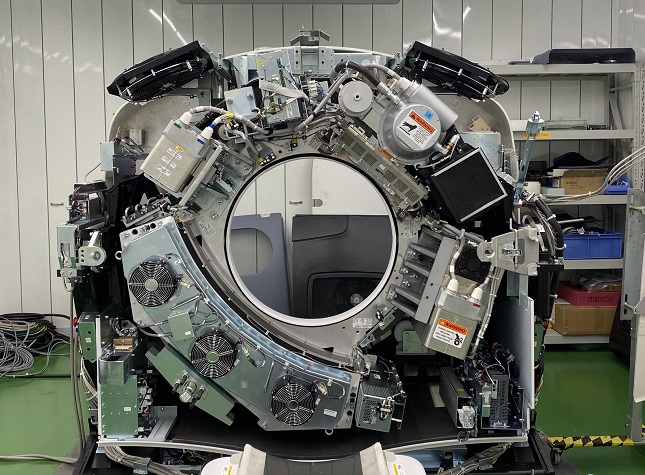
- Position the tube at 1 o'clock position for easy access to brake assembly.
Figure 1. Tube Position
- Disable the 120 VAC service switch.
- Remove the gantry left side, top and front covers. Connect the cover E-stop circuit to the terminators on the gantry.
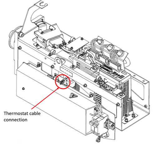
- Disconnect thermostat cable from connection on back side of resistor assembly. Refer to Figure 2.
Figure 2. Thermostat cable connection
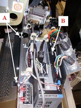
- Loosen cable clamp and disconnect brake resistor cable from X3 port of axial drive controller. Refer to Figure 3. Loosen and/or remove the side safety cover if needed for extra space when removing cable.note: Take note of the position of the resistor cable before disassembling. Different gantry models will have different routing for this cable.
- Remove existing brake resistor assembly from axial drive assembly using a 5mm hex wrench. Refer to Figure 3.
Figure 3. Axial drive cable connection and mounting points
 |
2 Installation of Brake Resistor Assembly on Assembly Frame, Cabling and Routing
Procedure
- Mount the resistor assembly to side of axial drive box with two (2) M6 screws, lock washers and flat washers using a 5mm hex wrench. Refer to Figure 3 and torque according to the table below.
- Connect thermostat cable to connection on back side of resistor assembly. Refer to Figure 2.
- Route resistor cable the same way it was routed on the previous assembly and connect into the X3 port of the axial drive. Refer to Figure 3. Tighten cable clamp around cable. Loosen and/or remove the side safety cover if needed for extra space when installing cable.
3 Reassembly of Gantry
Procedure
- Fasten the side safety cover on the tilting assembly if loosened or removed during previous steps.
- Install the gantry front cover, top and left side covers.
- Turn on the Axial drive, HVDC and 120VAC service switches from the service switch panel.
- Install the gantry right side cover.
4 Finalization
Procedure
- Run the System Scanning Test from the Functional Checks procedure list.