- Topic ID: id_17422979
- Version: 3.0
- Date: Apr 22, 2019 12:56:00 AM
Gantry Thermal Theory (Merc40)
1 Overview
To manage the gantry internal temperature, four control loops are used. These control loops include:
-
Detector Air Plenum fans (three fans)
-
Detector Strip Heaters (front and rear)
-
Gantry Top cover fans (two fans)
-
Inlet air heater
The TGPG and CDCB (CDAS DCB) boards coordinate the operation of these control loops to optimize the temperature at the Detector modules and rails.
-
The Gantry top cover fans and gantry heater are controlled by the TGPG via the stationary Common Fan Control (CFC) board.
-
The Plenum Fans are controlled by the CDCB via Common Fan and Heater Controller (CFHC).
-
The Detector rail heaters are controlled by the CFHC using set points established by the CDCB.
-
The CFHC and CDCB boards accept messages via an RS232 interface and control fans/heaters as required.
-
The CFHC board simply maintains the commanded value for fan speed and heater temperature. Changes to these values are calculated in the TGPG for the CFC and CDCB for the CFHC.
The TGPG sends configuration information to the CDCB. Then the CDCB provides configuration, and control information to the rotating side CFHC. By using variable-speed fans in the Detector plenum, the Cj M40 system mitigates the effects of the change in air temperature in the plenum, fan efficiency, system resistance and air density on the detector modules. The top cover fans are also variable speed to regulate and minimize variation in the gantry air temperature.
Figure 1. Gantry Thermal block diagram
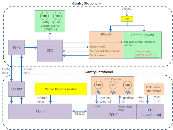
The Gantry contains 2 exhaust fans on the top covers, one gantry heater blower for controlling flow over the Gantry. There is a temperature sensor on the Heater blower exhaust.
The detector has 3 fans and 3 temperature sensors in the plenum, 2 rail heaters (Front and Rear), 3 rail temperature sensors on the Detector rail, and temperature sensors in each Chiclet. One FRDM module outputs 4 temp. data. Access to all of these devices except for the detector module temperature sensors is via a CFHC board, including detector rail heater and rail thermal sensors.
CDCB and CFHC communicates using Serial line (RS232C) every 2sec. interval for handling Chiclet temp. data and Plenum temp.data.
2 Stationary side control
The gantry stationary thermal devices are controlled by the thermal manager task on the TGPG. The TGPG reads and sends commands to the stationary side CFC. The TGPG gets temperature readings from the Detector plenum thermistors.
2.1 Gantry Heater Control
In the gantry heater blower Assy, the blower is always turned on with 120VAC supply. The heater temperature is controlled by TGPG via Stationary CFC that uses temperature feedback of thermistor in Heater Blower Assy. The thermal manager in the TGPG uses configuration file parameters to determine the behavior of the gantry heater. The TGPG checks the heater temperature at a rate which is determined by a configuration entry. The Heater control uses PID (Proportional Integral Derivative control) to keep the blowing air temperature to controlled value required for Plenum inlet temperature. Required control value is dynamic depending on the Gantry environmental temperature and its condition.
2.2 Heater Blower
Cj M40 Heater blower is different from previous Optima CT660 or VCT product. Merc40 Detector requires more precise temperature control, Heater capacity became bigger and the direction of air flow was changed. The following shows the new Heater Blower picture.
Figure 2. Heater Blower outlook
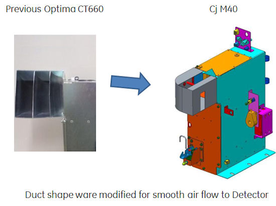
This Heater Blower has a self diagnostic feature. When CFC is powered up, Heater is heated up, start blowing and read the thermistor feedback (it doesn’t happen by reset). If the feedback is not value that is expected one, system will put error message in gesyslog.
Also Heater current error detection feature is implemented. This is to detect the heater current when heater command is ON. If the current is not flowed, error is put into gesyslog.
In both of case, system does not prohibit Patient scanning until Detector thermal error is detected.
2.3 Gantry Top Fan Control
The thermal manager task on the TGPG sends a message to the CDCB through the SCORP requesting plenum temperatures. The plenum temperature data is sent through a digital filter on the TGPG with the results then averaged together. The filtered average is used to determine the fan speeds for the gantry fans.
3 Rotating side control
Figure 3. Gantry Rotational thermal block diagram
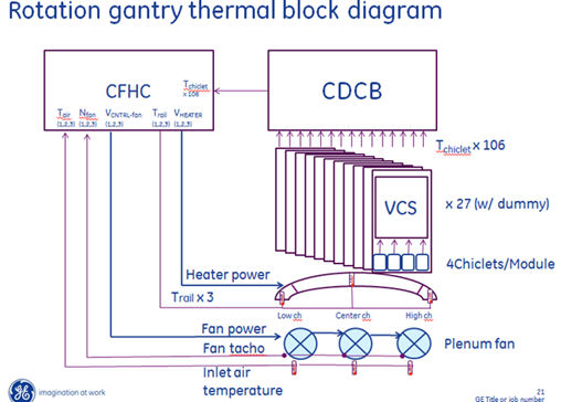
3.1 Plenum Fan Control
Plenum Fan rotation speed is controlled by CFHC. Input is all of Chiclet temperature. Based on the temperature, CFHC controls the rotation speed. Control algorithm is PID. Feedback signal is tachometer of Plenum Fan.
3.2 Rail Heater Control
Rail Heater Control is independent function. That exists in CFHC, but separate control task manages Rail Heater Control. The task receives the Rail thermal data from Rail Thermistor and control 48VDC heater current to Off/On.
3.3 Plenum Thermistor
Plenum Thermistor data is sent to CFC via DHCB -> CDCB -> SCORP -> TGPG -> CFC line. This is used for Heater Blower control.
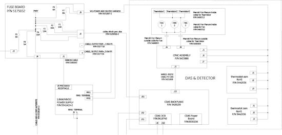
4 Detector Thermal Block Diagram
Figure 4. Detector Thermal Block Diagram
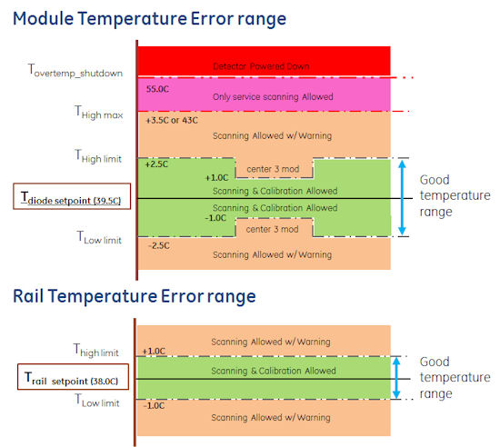
5 Module/Rail Temperature Error Range
Figure 5. Module/Rail Temperature Error range
6 Common Fan Controller (CFC)
Common Fan Controller (CFC) is used for controlling Gantry Top Fan and Heater Blower. This is different component that is used for previous Optima CT660 or VCT products. These three component provides required temperature air blow for Merc40 Detector. The input of this control comes from Plenum thermistor. The requirement of Plenum inlet air temperature is as follows.
-
Plenum Inlet air temp: 26 to 34 C deg. (@rotation) 28 to 34C deg. (@ parking)
-
Delta temp. between three temp. shall be smaller than 3 C deg.
7 Combined Fan and Heater Controller (CFHC)
Combined Fan and Heater Controller is the circuit board located beside Merc40 Detector. This has the function of Plenum Fan control and Rail heater control. Originally these functions were controlled by different board, CFC and DHCB at previous Optima CT660 and VCT series.