- Topic ID: id_17423031
- Version: 6.0
- Date: Jun 4, 2020 8:07:22 PM
Detector Heater Replacement (Front / Rear)
Prerequisites
Overview
This procedure defines the necessary steps to Remove and Install the Merc40 wide type heater (5456991-2).
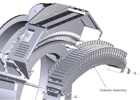
Perform the replacement of the heater under the detector is mounted on the gantry. The illustrations in this procedure should be used only as a guide.
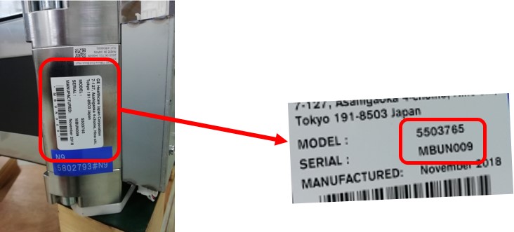
Heater replacement kit includes wide and slim heater, so identification of appropriate heater is required.
- Check Label on High channel side end block as shown in Figure 3.
- Verify MBU P/N in Table 7 to identify rail type.
- Once identify rail type, refer to Heater PN in Table 7 and choose appropriate heater for replacement.
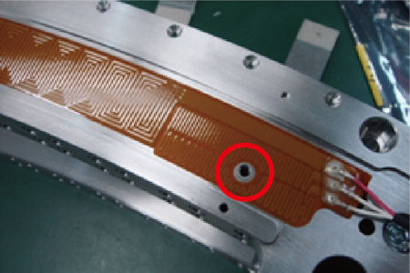
Figure 3. Label on High Channel Side End Block
1 Preparation
Procedure
- Move table to home position, fully out and down.
- Remove right side gantry cover.
Refer to Parts Replacement → Gantry → Enclosure → (Cover Removal Procedure).
- Stop the rotor of X-ray tube in case of Liquid Bearing Tube before HVDC off. Refer to Liquid Bearing Tube Rotor stop procedure for details.
- Turn OFF the Axial Drive and HVDC switches on the gantry’s Service Switch Panel.
- Position the detector at 12 o'clock and lock gantry rotation.
- Turn OFF the 120 VAC switch on the gantry’s Service Switch Panel.
- Remove the gantry left side cover, top covers and front cover.
- Cover the Tube Collimator port to protect it against dropped tools or screws. (Cloth or any other available item)
- Remove the Air Plenum as shown in Detector Air Plenum Removal/Installation.
- Remove 3 thermistors as shown in Thermistor Replacement.
- After completing Preparation procedure, go on to the next step according to the instruction in Table 8.
2 Removal Procedure (Front)
Procedure
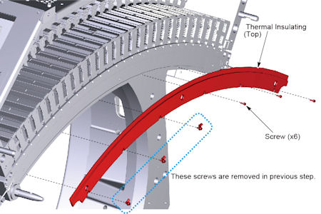
- Remove 6 screws holding the thermal insulating top to the detector, and remove the thermal insulating top.
Figure 4. Thermal Insulating - Top
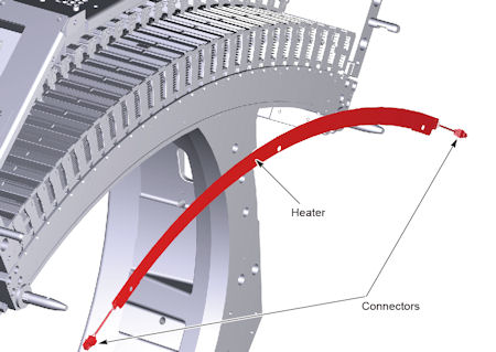
- Disconnect 2 cable connectors of heater, and remove the heater from top collimator rail of the detector.
Figure 5. Detector Heater
3 Remove Adhesive
Procedure
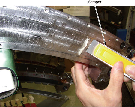
- Moisten the remaining (old) adhesive on the top collimator rail by alcohol pads (or equivalent).
- Scrape the softened (macerate) adhesive off using a scraper.
Figure 6. Top Collimator Rail
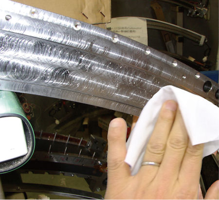
- Wipe off the remaining (old) adhesive completely from the attaching surface of the top collimator rail using alcohol pads (or equivalent).
Figure 7. Top Collimator Rail
- After completing Remove Adhesive procedure, go on to the next step according to the instruction in Table 8.
4 Heater Installation Procedure (Wide Type Heater)
Procedure
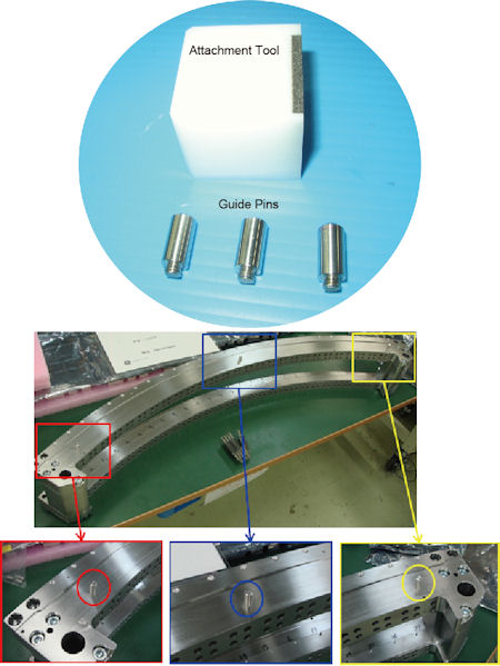
- Set 3 guide pins to the top collimator rail.
Figure 8. Heater Attachment Tools
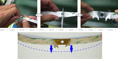
- Peel the backing sheet a few centimeters at the center portion of the heater, and make a cut in the backing sheet, then bend the backing sheet toward the outside of arc of the heater.
Figure 9. Backing Sheet of the Heater
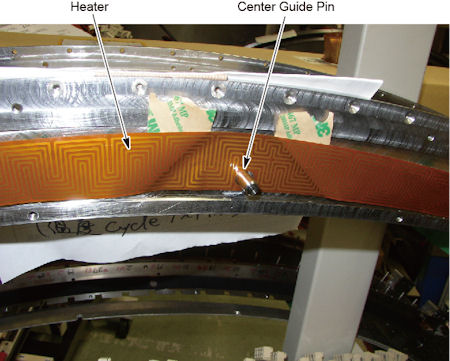
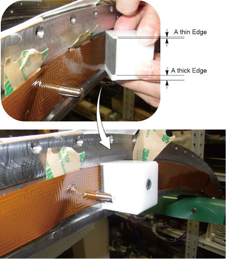
- Set the center hole of the heater to the center guide pin temporarily, and put it to the others guide pins.
Figure 10. Center Hole of the Heater
- At the right portion of the detector (high channel side) :
- Peel the backing sheet a few centimeters, and set the attachment tool to the collimator rail, to adjust the position of the heater.
Figure 11. Attachment Tool Setting
- notice
- Peel away the backing sheet of the heater gradually, and move the attachment tool along the groove in the side of the collimator rail to attach the heater to the collimator rail.
Figure 12. Heater Attachment

- The attachment is completed at the following right end portion of the heater, stop use of the attachment tool.
Figure 13. Heater and Attachment Tool
- Remove the guide pin at the right side of the detector.
- Press the heater by finger to attach it to the collimator rail.
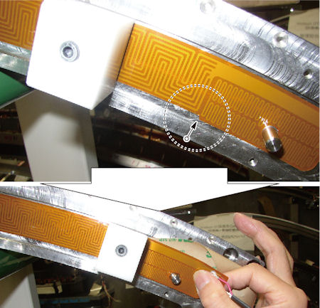
- Verify that the heater does not interfere the thermistor hole on the detector.
If there is interference with the thermistor hole, remove the heater, and install another heater.
Figure 14. Position of the Heater

- Peel the backing sheet a few centimeters, and set the attachment tool to the collimator rail, to adjust the position of the heater.
- At the left portion of the detector (low channel side) :
- Remove the center guide pin.
- Attach the heater of the left portion according to Step 4.
- Press and rub the heater to check if there is no air in the joint area and there is no abnormal noise, and verify that the heater is securely attached to the detector.
5 Front Re-installation
Procedure
- Connect the 2 cable connector of heater.
- Install the thermal insulating top to the detector, and tighten the 6 screws temporarily.
- After completing Front Re-installation procedure, go on to the next step according to the instruction in Table 8.
6 Removal Procedure (Rear)
Procedure
- Remove DAS assembly, and make sure the DAS assembly is set on a flat clean surface and not on top of any small objects.
Figure 15. DAS Assembly Removal
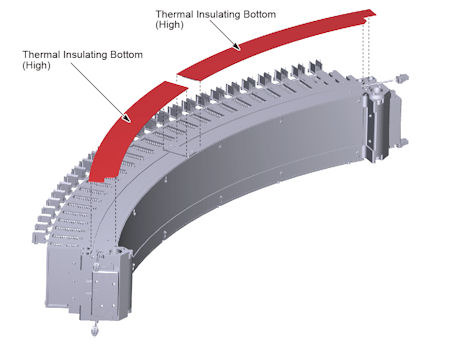
- Remove a thermal insulating bottom (High and Low) from the bottom collimator rail.
Figure 16. Thermal Insulating Bottom (High and Low) Removal
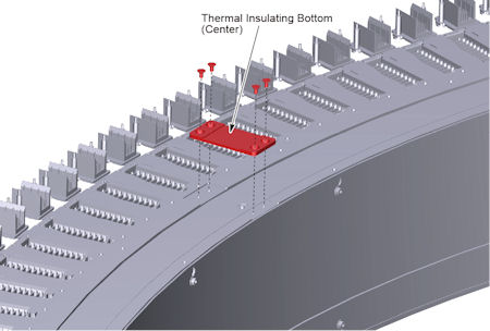
- Remove 4 screws holding the thermal insulating bottom (Center) to the bottom collimator rail, remove the thermal insulating bottom (Center).
Figure 17. Thermal Insulating Bottom (Center) Removal
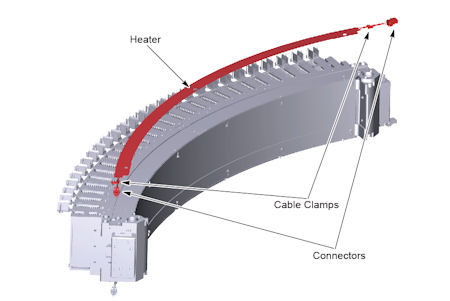
- Remove 2 cable clamps and disconnect 2 cable connectors of heater, then remove the heater from bottom collimator rail of the detector.
Figure 18. Heater Removal
7 Remove Adhesive (Rear)
Procedure
- Remove adhesive on the top collimator rail, as shown in Remove Adhesive.
- After completing Remove Adhesive (Rear) procedure, go on to the next step according to the instruction in Table 8.
8 Rear Heater Installation Procedure (Wide Type Heater)
Procedure
- Install heater to the collimator rail, as shown in Heater Installation Procedure (Wide Type Heater).
9 Rear Re-installation
Procedure
- Connect the 2 cable connector of heater, and fix the heater cables to the bottom collimator rail using the 2 cable clamps.
- Install the thermal insulating bottom (center), and tighten the 4 screws to fix the thermal insulating.
- Attach the thermal insulating bottom (high and low) to the bottom collimator rail.
- Install the DAS assembly.
10 Gantry Reassembly
Procedure
- Install the 3 thermistors as shown in Thermistor Replacement, and tighten the 6 screws of the thermal insulating top.
- Install the Air Plenum as shown in Detector Air Plenum Removal/Installation.
- Make sure the Axial Drive, HVDC and 120 VAC switches on the gantry’s Service Switch Panel are OFF.
- Release the gantry rotational lock and install gantry covers,
all except the right side cover.
Refer to Replacement → Gantry → Enclosure → (Cover Removal Procedures).
- Turn on the 120 VAC, HVDC and Axial drive service switches.
- Install gantry right side cover.
11 Finalization
Procedure
- Allow the detector to warm up while monitoring the detector temps to make sure all 3 zones are coming up to temperature. The detector may take up to 45 minutes to come up to temperature. Check Detector temps to make sure the detector warms up to 38 °C and stays there. Detector warm up may take up to 45 minutes.
- Perform a Fastcal.
- Perform the [Quality Assurance Test] from the [Functional Checks] menu of the service manual to ensure system operation.