- Topic ID: id_15460170
- Version: 5.0
- Date: Jan 20, 2020 8:34:35 PM
Detector Air Plenum Removal and Installation
Prerequisites
Overview
This procedure defines the necessary steps to Remove and Install the Detector Air Plenum Assembly.
1 Preparation
Procedure
- Move table to home position, fully out and down.
- Remove right side gantry cover.
Refer to Parts Replacement → Gantry → Enclosure → (Cover Removal Procedure).
- Stop the rotor of X-ray tube in case of Liquid Bearing Tube before HVDC off. Refer to Liquid Bearing Tube Rotor stop procedure for details.
- Turn OFF the Axial Drive and HVDC switches on the gantry’s Service Switch Panel.
- Position the detector at 12 o'clock and lock gantry rotation.
- Turn OFF the 120 VAC switch on the gantry’s Service Switch Panel.
- Remove the gantry left side cover, top covers and front cover.
2 Removal Procedure
Procedure
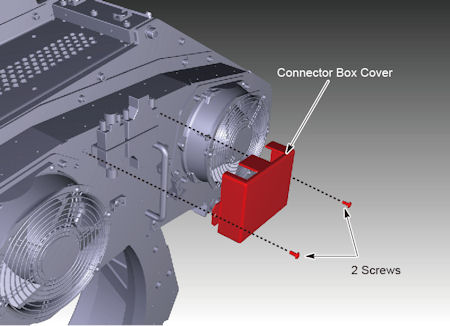
- Remove the connector box cover.
Figure 1. Connector Box Cover Removal
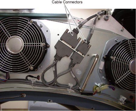
- Disconnect two cable connectors.
Figure 2. Cable Connectors
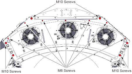
- Remove M6 screws (x 7) and M10 screws (x 6) holding the air
plenum to the DAS assembly.
Figure 3. M6 and M10 Screws
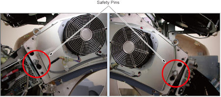
- Disengage safety pins on both sides of plenum.
Figure 4. Safety Pins
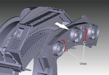
- Hold the grips on the plenum with both hands, and remove the
plenum straight away from the gantry to avoid bending the plenum alignment
pins on either side of the plenum.
Figure 5. Air Plenum Removal
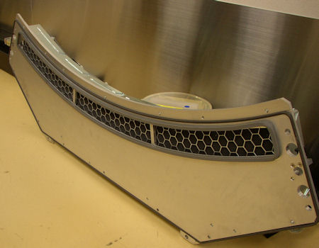
- Make sure the plenum is set on a flat clean surface and not
on top of any small objects that can poke the EMC screen.
Figure 6. Backside of the Plenum
3 Installation Procedure
Procedure
- Install the air plenum housing being careful not to hit the EMC mesh on the backside of the plenum during installation. Make sure no cabling is caught between the detector casting and the air plenum.
- Engage safety pins on both sides of plenum.
- Torque the M10 screws to the value shown in Table 7.
- Torque the M6 screws to the value shown in Table 8.
- Reconnect the two cable connectors.
- Install the connector box cover, and torque the screws to the
value shown in Table 9.
4 Finalization
Procedure
- When power is restored to the gantry, check to make sure all 3 plenum fans are running. Use a piece of paper or similar object to make sure fans are pulling air into the plenum. A fan that is not running will still have the fan blades moving as air is pushed back out of the plenum through that fan port.