- Topic ID: id_11039062
- Version: 3.0
- Date: May 23, 2022 11:26:05 PM
Vyper DAS Backplane Board (DBP) Replacement
Prerequisites
This procedure defines the replacement process for the Vyper DAS backplane board (DBP).
1 Preparation
Procedure
- Move the table cradle to the home position, and position the table to its lowest elevation.
- Remove the gantry right side cover.
- notice
- Turn OFF Axial Enable, HVDC, and 120VAC switches on the service switch panel.
- Remove the gantry side, top and front covers.
- Position the DAS at the 12 o'clock position.
- Lock the gantry in position using the rotational lock.
 |
2 DAS Backplane Board Removal
Procedure
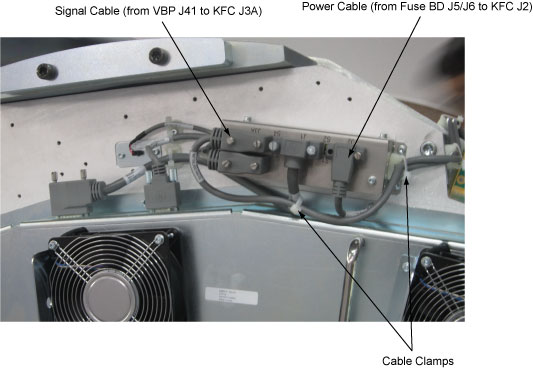
- Release the cable clamps holding the fan controller power cable and signal cable.
- Disconnect the cable connectors from the KFC J2 and J3A.
Figure 1. Release the Cable Clamps and Disconnect Cable Connectors
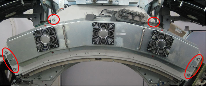
- Demount the Vyper plenum ASM by unscrewing its six M10 head
cap screws.
Figure 2. Vyper Plenum ASM Removal
- notice
- Remove the following boards from the backplane board.
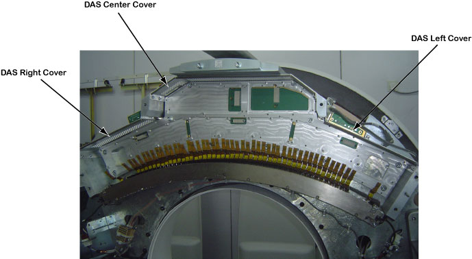
- Remove the DAS covers (left, center and right) from the DAS
mounting plate assy.
Figure 3. DAS Covers Removal
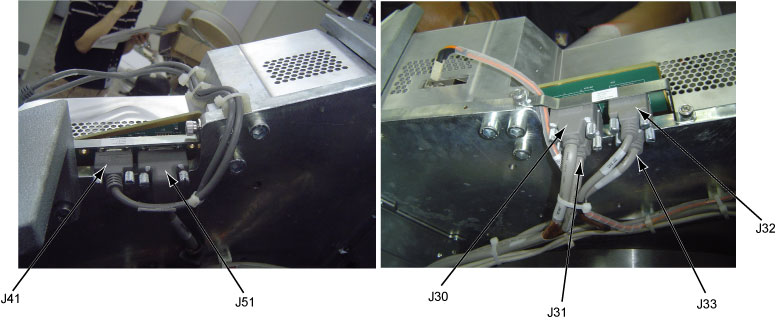
- Disconnect the following cable connectors from the DAS backplane
board.
-
5423496: KFC Assy J3A to DBP J41
-
5343002-5: Fuse Board J3 to DBP J51
-
2333314-3: Collimator J1 to DBP J30
-
2333309-5: ORP J7 to DBP J31
-
2377649-2: JEDI Power Unit J5 to DBP J32
-
5343008: DHCB J2 to DBP J33
Figure 4. Disconnect Cable Connectors
-
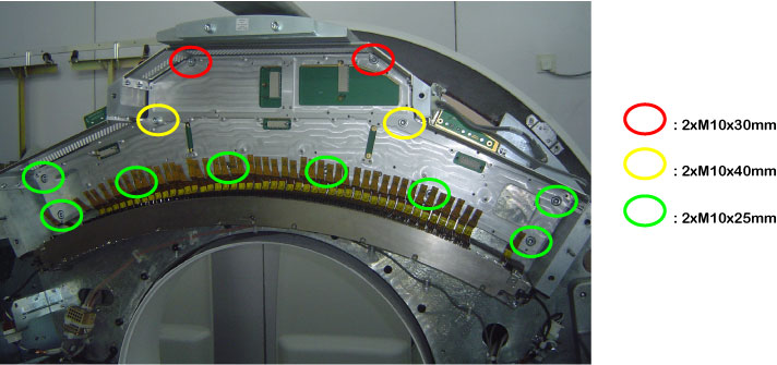
- Demount the DAS frame together with the DAS backplane board
from the DAS mounting plate by unscrewing twelve mounting screws.
Figure 5. DAS Frame and DBP Removal
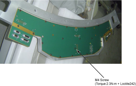
- Remove the DAS backplane board from the DAS frame by unscrewing its twenty-three screws.
- Get new DAS backplane board from anti-static bag and secure
it to the DAS frame by screwing its twenty-three screws. (Torque:
2.3N-m)note:
Only one screw need to use Loctite242. (See Figure 6)
Figure 6. Secure DBP Board
- Remount the DAS frame together with the DAS backplane board
to the DAS mounting plate by securing twelve mounting screws.note:
The flex cables are very sensitive, so keep extreme care when mounting the DAS frame.
- Reinstall the DAS covers (left, center and right) to the DAS mounting plate assy.
- Reconnect all cable connectors to the DAS backplane board.
- Reinstall the DAS interface boards, DAS power board and DAS
control board to the DAS backplane board.
Refer to the following procedure:
- Remount the Vyper plenum ASM by securing its six M10 head cap screws with Loctite 242. (Torque: 38.4N-m)
- Reconnect the cable connectors to the KFC J2 and J3A and tie cables with cable clamps.
- Disengage the rotational lock.
- Turn on Axial Enable, HVDC, and 120VAC switches.
3 Finalization
Procedure
- Verify proper functionality:
- Run at least 10 passes of Scan Data Path Diagnostic.
- Take 10 I/Q scans of 20cm phantom.
- Verify fault or reason to replace the board now passes.
- Reassemble gantry covers.