- Topic ID: id_11039059
- Version: 3.0
- Date: May 23, 2022 11:24:52 PM
Vyper DAS Control Board (DCB) Replacement
Prerequisites
This procedure defines the replacement process for the Vyper DAS control board (DCB).
1 Preparation
Procedure
- Move the table cradle to the home position, and position the table to its lowest elevation.
- Remove the gantry right side cover.
- notice
- Turn OFF Axial Enable, HVDC, and 120VAC switches on the service switch panel.
- Remove the gantry side, top and front covers.
- Position the DAS at the 12 o'clock position.
- Lock the gantry in position using the rotational lock.
 |
2 Board Removal/Installation
Procedure
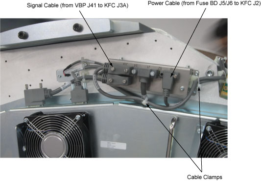
- Release the cable clamps holding the fan controller power cable and signal cable.
- Disconnect the cable connectors from the KFC J2 and J3A.
Figure 1. Release the Cable Clamps and Disconnect Cable Connectors
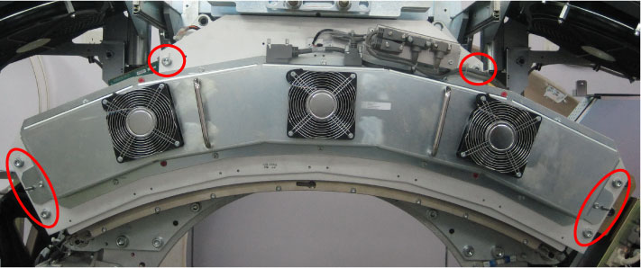
- Demount the Vyper plenum ASM by unscrewing its six M10 head
cap screws.
Figure 2. Vyper Plenum ASM Removal
- notice
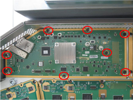
- Disconnect the optical fiber from the DCB.
- Remove eight screws from the DCB.
Figure 3. Screws Removal
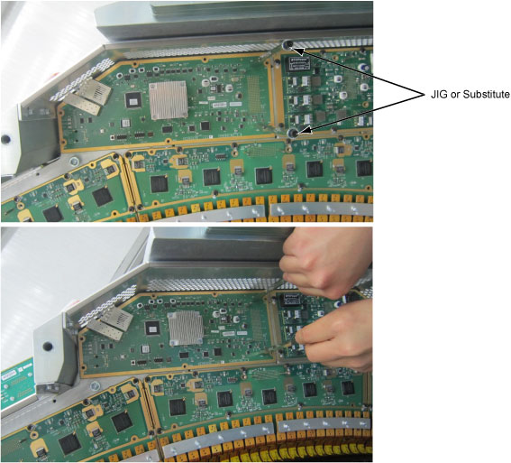
- Install two board handle JIGs (6488042, shipped with system
shipping collector) onto the DCB, then pull the DCB from the DAS backplane
(DBP) by holding JIGs.
Figure 4. DAS Control Board Removal
- Get new DCB from anti-static bag.
- Let the locating pins through DCB, then insert pinouts of DCB to DBP.
- Secure all the screws. Torque M4 hex screws to 2.3N-m.
- Reconnect the optical fiber to DCB.
- Remount the Vyper plenum ASM by securing its six M10 head cap screws with Loctite 242. (Torque: 38.4N-m)
- Reconnect the cable connectors to the KFC J2 and J3A and tie cables with cable clamps.
- Disengage the rotational lock.
- Turn on Axial Enable, HVDC, and 120VAC switches.
3 Finalization
Procedure
- Perform Flashdowload.
- Verify proper functionality:
- Run at least 10 passes of Scan Data Path Diagnostic.
- Take 10 I/Q scans of the 20cm phantom.
- Verify fault or reason to replace the board now passes.
- Reassemble gantry covers.