- Topic ID: id_17423438
- Version: 3.0
- Date: Jan 20, 2020 8:32:21 PM
Pump Assembly Replacement
Prerequisites
Overview
Procedure
- notice
- Remove the left side maintenance cover from the Gantry.
- Raise the Table to its highest position.note:
The maximum height is approximately 950mm measured from the Table frame to the lowest point of the cradles top surface.
- Remove the following covers and component:
-
Top Covers (Left and Right) (Refer to Table Covers Removal)
-
Middle Side Covers (Left and Right) Refer to Table Covers Removal)
-
Middle Rear Cover (Two(2) Screws)
-
Cradle (Refer to Cradle)
-
Left and Right Rail Covers (Four(4)x2 Screws)
-
Cradle Tray (Six(6) Screws)
-
- "Remove power from Table by turning off “120VAC”, “Axial Drive” and “HVDC” switches on the service switch panel."
- Disconnect the power connector from the oil pump.
- Disconnect the 4–line connector leading from the NPSUB to the pump capacitor.
- Measure the resistance across the terminals of the pump capacitor
using a DVM. If the resistance increases, the capacitor, the capacitor
should be functional. If the resistance is zero or infinite, the capacitor
is melted down or shorted open. In this case replace the Pump Capacitor.note:
If you have replaced the Table pump capacitor, maybe the pump need no replacement. Check to see if the pump is operational after replacing the capacitor.
Figure 1. Table Pump / Capacitor Connections
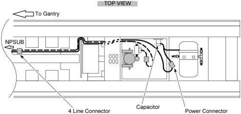
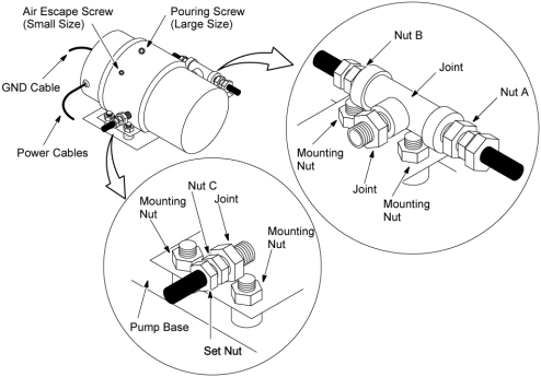
- Disconnect the GND cable from the oil pump.
- Disconnect hose nuts A, B, and C shown in Figure 2. A small amount of oil may leak out, but this is acceptable.
- Transfer the hose joints from the old pump to the new one.
- Remove the pump assy by unscrewing the two screws holding it to the Table base.
- Remove the pump base by unscrewing the four nuts, and transfer
the pump base to the new pump.
Figure 2. Table Oil Pump
- Install the new oil pump assy by referring toStep 9 through Step 5.
Verify that the hose configuration is correct.
- Add oil to the pump by referring to the following section:
- Lower the Table to its lower limit position.
- Raise the Table to its highest position.
- Repeat Step 15. and Step 16. a few times to remove any air in the cylinder. Stop this procedure at the Table upper limit position.
- Restore the Table to original configuration.
 |
Finalization
No finalization steps.