- Topic ID: id_11038953
- Version: 5.0
- Date: May 20, 2022 6:19:52 AM
Hydraulic Cylinder Replacement
Prerequisites
Procedure
- notice
- Remove the following covers and component:
-
Top Covers (Left and Right side) (Refer to Table Covers Removal)
-
Middle Side Cover (Left and Right side) (Refer to Table Covers Removal)
-
Cradle (Refer to Cradle)
-
Rear Cover (Four(4) Screws)
-
Left and Right Rail Covers (Four(4)x2 Screws)
-
Cradle Tray (Six(6) Screws)
-
Bottom Covers (front and bottom) (Refer to Table Covers Removal)
-
- Raise the Table to its highest position. note: If the Table up/down movement is inoperative, use the service power cable to raise the Table (refer to Enforced Table Elevation).
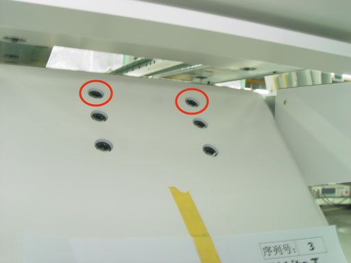
- Unscrewing two support bolts fixed on the upper of the U-column block. Refer to Figure 1.
Figure 1. Support bolts
- Set the table height to approx. 880 mm (from ground to table cradle), remove power from Table by turning off “120VAC”, “Axial Drive” and “HVDC” switches on the service switch panel.
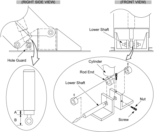
- Remove the small metal hole guard using Philips driver from the inside of the lower left and right sides support.
- Remove the GTCB board (refer to GTCB Assembly Replacement), and then release the two screws which tighten the lower draft.
- Attach the support tool as follows:note: When using the support tool, the adjuster should be partially extended, about 5cm, before supporting the Table.
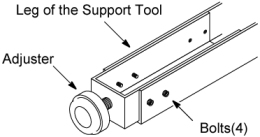
- Assemble the Table Support Tool.
Figure 2. Leg of the Support Tool
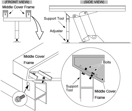
- Attach the support tool to the undersurface of the Table on
the side farthest from the Gantry using the four bolts currently screwed
into the bottom of the Middle Cover frame. Lower the Table onto the
support.
Figure 3. Table Support Tool
- Assemble the Table Support Tool.
- Remove the lower shaft and slide it out of the cylinder rod end hole.
- Disconnect all cables from the cylinder to the other components.
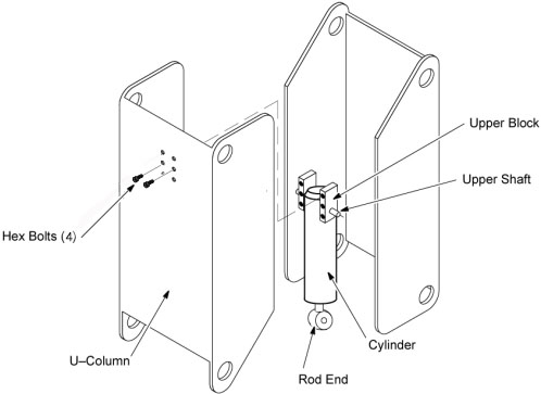
- Disengage the upper blocks from the U–column by unscrewing rest
four support bolts by L wrench
Figure 4. Cylinder Removal
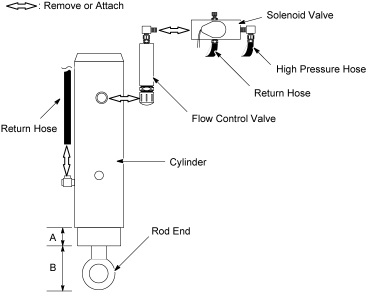
- Remove the oil return hose from the hydraulic cylinder.
- Remove the solenoid valve from the cylinder.
- Remove the flow control valve using 20mm wrench from the old cylinder.
- Remove the rod and the cylinder together.
- Measure the distance “B”: between the rod end and the rod base of the old cylinder.
- Adjust the new rod to the same distance, “B”, as the old rod.
- Install the new rod and cylinder using the lower shaft. Tighten the lower shaft into place.
- Return the hole guard to the side support and screw it into
place.
Figure 5. Metal Hole Guard and Lower Shaft
- Attach to the new cylinder using sealing tape.
Verify that the flow control valve should be at an angle of approximately 10° ~ 30° to the cylinder.
- Attach the solenoid valve to the new cylinder.
- Attach the return hose to the new cylinder.
Figure 6. Valve Removal/Attachment
- Verify that all piping and hosing is in the proper configuration and will not catch.
- Add oil to the pump by referring to the following section:
- Engage the upper blocks from the U–column by screwing the bottom of four support bolts by L wrench
- Install GTCB Board.
- Loosen the adjuster of the support tool and carefully remove the support tool from under the table.
- Turn on “120VAC”, “Axial Drive” and “HVDC” switches on the service switch panel."
- Raise and lower the Table repeatedly and Check the following:
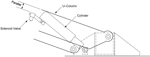
- Visually check that the solenoid valve and U–Column surface is parallel.
- Verify that the hosing does not catch or pull excessively.
Figure 7. Solenoid Valve Configuration
- Raise the Table to the highest position.
- Screwing the top two support bolts on the upper U-column block
- Restore the Table to original configuration.
 |
Finalization
No finalization steps.