- Topic ID: id_16157638
- Version: 1.0
- Date: Jul 7, 2018 4:41:52 PM
ORP Replacement
Prerequisites
Overview
This document provides the necessary steps to replace and configure the Onboard Rotation Processor Unit (ORP) for imaging.
1 ORP Assembly Removal
Procedure
- Verify ORP type.
- Open a shell
- Type: rlogin orp.
- Type: d 0x10000000
- The content of 0x10000000 to 0x1000000B is for ORP/SCORP/ORPSV
board.

- If the content is 5437621, the board is ORPSV, others are SCORP.
- Move table to home position.
- Remove gantry right side cover.
- Turn off [HVDC ENABLE], [AXIAL DRIVE ENABLE] and [120 VAC ENABLE] switches on Service Switch panel.
- Remove power to system. See Equipment Service - Lockout-Tagout-PPE from Safety section.
- Remove scan window, gantry left side cover, gantry top covers and gantry front cover.
- Rotate gantry such that ORP assembly is in 2 o'clock position.
- Engage rotational lock.
- Detach and remove cable clamps from top of ORP Assembly with a 3mm Allen Wrench.
- Cut tie-wraps holding cables to the ORP box.
Figure 1. ORP Assembly
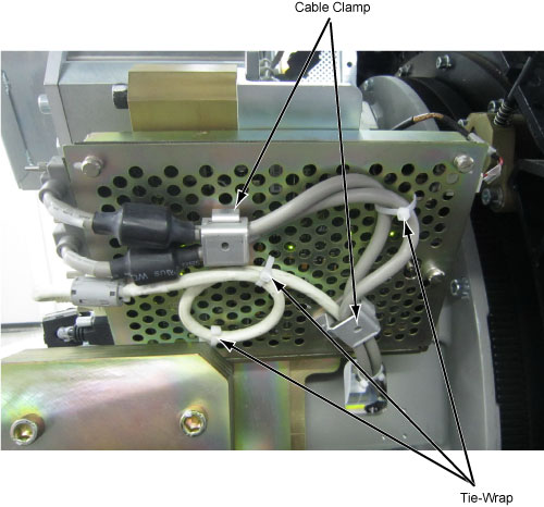
- Disconnect four front cables and one rear cable from ORP Assembly.
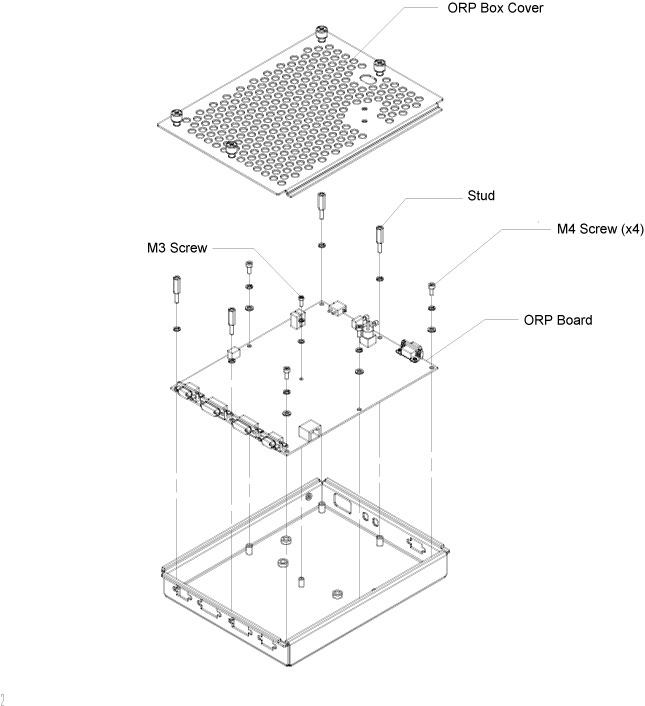
- Open the ORP box cover by loosening its four screws.
- Remove the ORP board from the box by unscrewing screws and studs.
Figure 2. ORP Board Removal
2 ORP Assembly Installation
Procedure
- Get the new ORP board and install it to the ORP box by screwing its four M4 screws and one M3 screw.
- Install four studs to the ORP board. (See Figure 2)
- Secure the ORP box cover.
- Reconnect four front cables and one rear cable to ORP Assembly.
- Attach cable clamps and tie-wraps to re-tie cables to ORP box cover.
- Disengage rotational lock.
- Restore power to system. See Equipment Service - Lockout-Tagout-PPE from Safety section.
- From Console Unix Shell prompt, type touch /usr/g/fw/orpFtp and press ENTER.
- Turn on 120 VAC ENABLE, AXIAL DRIVE ENABLE, and HVDC ENABLE switches on Service Switch Panel.
- Press ESTOP RESET on Service Switch panel and wait until scan hardware is reset.
3 Setup, Checks, Alignments, and Calibrations
Procedure
- FLASH Download
- Turn off [HVDC ENABLE], [AXIAL DRIVE ENABLE] and [120 VAC ENABLE] switches on Service Switch panel.
- Install gantry front, top and left side covers and scan window.
- Turn on 120 VAC ENABLE, AXIAL DRIVE ENABLE, and HVDC ENABLE switches on Service Switch Panel.
- Press ESTOP RESET on Service Switch panel and wait until scan hardware is reset.
- Install gantry right side cover.
4 Finalization
Procedure
- Tube Warmup
- System Scanning Test
- Save Generator Runtime Parameters (See Save Restore Generator Runtime Parameters)
- Save System State