- Topic ID: id_17479544
- Version: 1.0
- Date: Aug 28, 2018 3:56:07 PM
Heat Blower Sub–Component Replacement
Prerequisites
Overview
This procedure defines the replacement process for the heater, thermistor probe and blower.
Figure 1. Heater
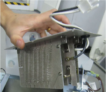
Figure 2. Thermistor Probe
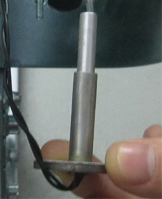
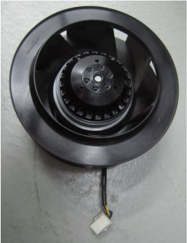
Figure 3. 120VAC Blower Assembly
1 Preparation
Procedure
- Move the table cradle to the home position, and position the table to its lowest elevation.
- Remove the gantry right side cover and disable “Axial Drive”, "HVDC" and "120VAC" switches from the service switch panel.
- Remove the gantry left, top and front covers, refer to Replacement > Gantry > Enclosure > Cover Removal Procedure.
- Remove the gantry heat blower assembly from the gantry by referring to Heat Blower ASM Replacement.
2 Heater
Procedure
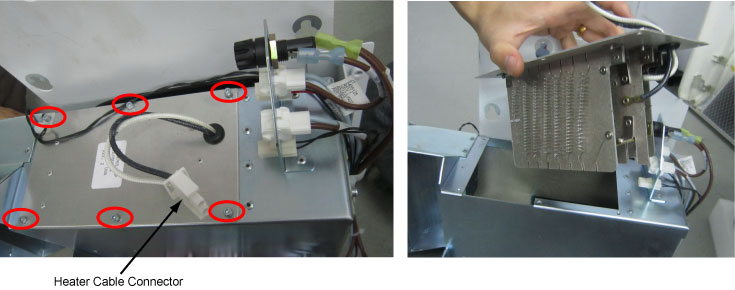
- Disconnect the heater cable connector. (See Figure 4)
- Remove the defective heater by unscrewing its six screws.
Figure 4. Heater Removal
- Get the new heater and secure it.
- Reconnect the heater cable connector.
3 Thermistor Probe
Procedure
- Disconnect the heater cable connector, then remove the thermistor
probe cable connector from the bracket.
Figure 5. Thermistor Probe Cable Connector
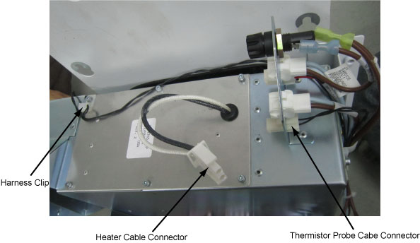
- Remove the thermistor probe cable from the harness clip. (See Figure 5)
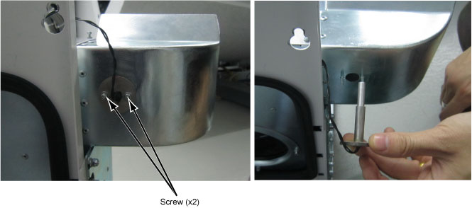
- Remove the defective thermistor probe by unscrewing its two
screws.
Figure 6. Thermistor Probe Removal
- Get the new thermistor probe and secure it.
- Re-fix the thermistor probe cable to the harness chip, and reconnect the thermistor probe cable and the heater cable.
4 120VAC Blower Assembly
Procedure
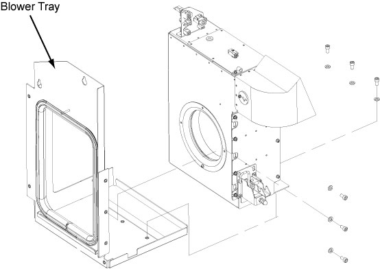
- Remove the blower tray by unscrewing its six M6 screws.
Figure 7. Blower Tray
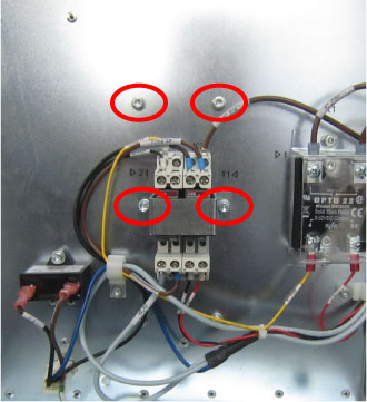
- Remove the blower box cover by unscrewing its five screws (Red)
and four nuts (Blue).
Figure 8. Remove Blower Box Cover
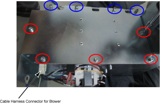
- Disconnect the blower cable harness connector. (See Figure 8)
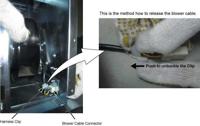
- Remove the blower cable connector from the blower box and remove
the blower cable from the harness clip. (See Figure 9)note:
Release the blower cable from the harness chip by referring to method which is shown in Figure 9.
Figure 9. Release Blower Cable
- Remove the blower assembly from the blower box by unscrewing
its four screws.
Figure 10. Blower Screws
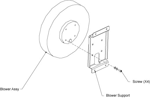
- Disassemble the blower support bracket from the blower assembly,
then assemble it to the new blower assembly.
Figure 11. Blower Support Bracket
- Assemble the blower assembly to the blower box by screwing its four screws, and fix the blower cable with harness chip.
- Reconnect the blower cable.
- Install the blower box cover by screwing its five screws and four nuts which are removed in Step 2.
- Reassembly the blower tray to the blower assembly. (Torque: 7.9N.m)
5 Finalization
Procedure
- Reassemble the gantry heat blower assembly to the gantry by referring to Heat Blower ASM Replacement.
- Restore power to the system.
- Verify that the heat blower assembly is operating normally.
- Restore the gantry to original configuration.