- Topic ID: task_wtk_vxm_zkb
- Version: 2.0
- Date: Jun 10, 2020 2:30:38 AM
Tube Fan Equipped Replacement
Prerequisites
Overview
This procedure defines the steps necessary to replace the stationary side Fan Control Module.
Procedure
- Move table to its lowest elevation.
- Remove the gantry right side cover and disable “Axial Drive”, “HVDC” and “120VAC” switches from the service switch panel.
- Remove gantry covers as required.

 danger
- Position the Tube at 3 o'clock and engage gantry rotational lock.
- Remove the Tube by following the procedure in Tube Replacement.
- Keep the Tube in steady position.
- Disconnect the fan connector from the fan to be replaced.
- caution
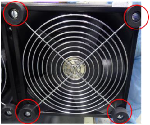
- Remove all four screws of grill in diagonal sequence and remove the grill as shown in below figure.
Figure 1. Removing Grill Screws and Grill
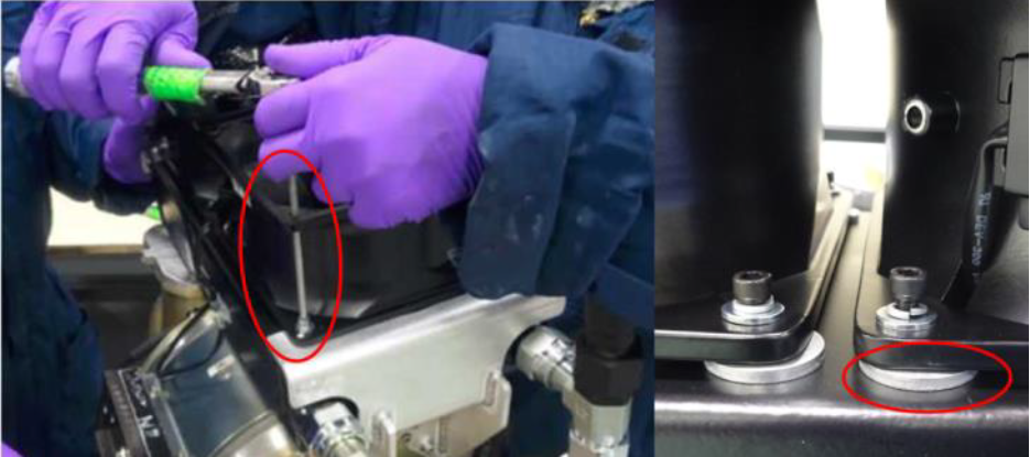
- Remove all four screws of fan in diagonal sequence as shown in Figure 2, take care of spacers so that they do not fall in heat exchanger.
Figure 2. Remove Fan Screws
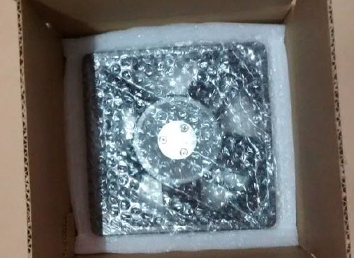
- Unpack new fan (5335802) from the packaging box (5749934) and check for any physical damages.
Figure 3. Fan Inside Packaging Box
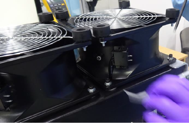
- Place the new fan on the bracket along with spacers in such a way the connector pins are oriented as shown in Figure 4.note:
Hardware to be used:
Fresh: Fan, Fan Screws
Reuse: Lock Washers, Flat Washers, Spacers, Grill, Grill Screws, Pads
Figure 4. Fan Positioning
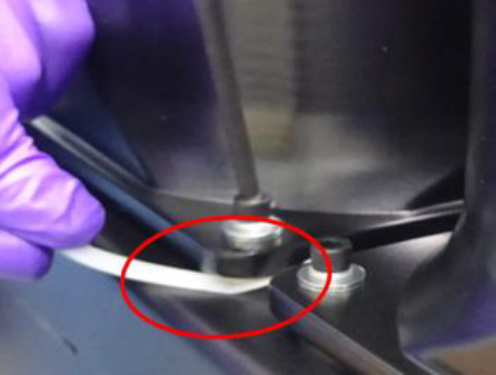
- Apply a small drop of Loctite 242 on new screw threads provided in packaging box, reuse lock and flat washers (Torque: 6±0.5Nm), make sure spacers are placed properly without projecting out. (See Figure 5)
Figure 5. Keep Spacer in Place while Tightening Fan Screws
- Place grill and tighten screws (Torque: 1.7±0.1Nm) with bumper. (See Figure 6)
Figure 6. After Putting Grill
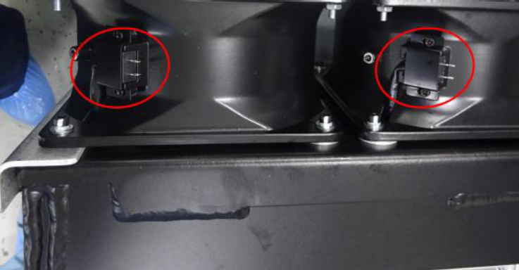
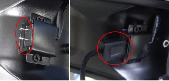
- Ensure there are no damages for the fan pins and connect the fan cables as shown in Figure 7.
Figure 7. Fan Cable Connections
- Re-install the Tube by following the procedure in Tube Replacement.
Finalization
- Verify that the tube fans are operating normally.
- Restore the gantry original configuration.