- Topic ID: id_17423123
- Version: 3.0
- Date: Jan 20, 2020 8:34:11 PM
Elevation Characterization Procedures
Prerequisites
Overview
1 Elevation Characterization
Procedure
- Move the cradle to the OUT limit position.
- Remove power from Table by turning off “HVDC”, “120VAC” and “Axial Drive” switches on the service switch panel.
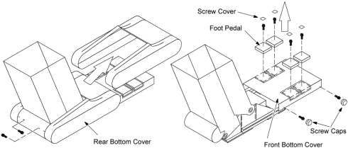
- Move the front and rear bottom covers as follows:
- Remove two screw caps from the rear bottom cover.
- Unscrew two screws, and remove the rear bottom cover.
- Remove four screw covers from the foot pedals.
- Unscrew four Allen screws, and remove the four pedals.
- Unscrew four screws, and remove the front bottom cover.
Figure 1. Front and Rear Bottom Covers
- Turn on the power of 120 VAC
- Set the service switch (MODE_SEL) to the SERVICE to enter the service mode.
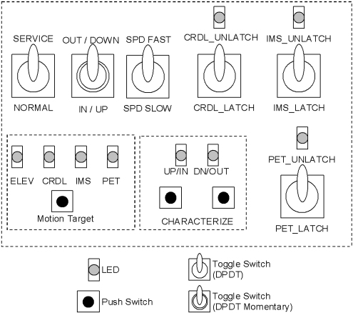
- Confirm that the “ELEV” LED on the GTCB board lights
up. If it doesn't light up, press the “Motion Target”
button until “ELEV” LED is ON.
Figure 2. LED's on GTCB
- Press and hold the service switch (ACTION) to the IN/UP position to move the table to the mechanical UP-limit position.
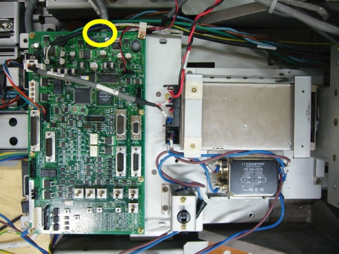
- Confirm that the “POT_ADJ UP” LED (Green) lights
up. If it doesn't light up, perform Height Potentiometer Adjustment
(refer to Height Potentiometer Adjustment).
Figure 3. POT_ADJ UP LED
- Press the two “Characterize” Buttons at the same time to start characterization.
- Confirm that the “UP/IN” LED lights up.
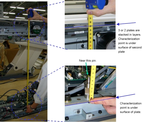
- Using the Service Switches, move the table at 950 +/- 0.5mm
of the distance between characterization points as shown in illustration
below.
Figure 4. Characterization Points
- Press the two “Characterize” Buttons at the same time.
- Confirm that the “DOWN/OUT” LED is ON.
- Using the Service Switch (ACTION), move the table at 650 ± 0.5mm of the distance between characterization points.
- Press the two “Characterize” Buttons at the same time to start characterization.
- Confirm that both of “UP/IN” LED and “DOWN/OUT” LED are ON.
- Using the Service Switch, move the table to the mechanical down-limit position.
- Press the two “Characterize” Buttons at the same time.
- 5 - 10 seconds later (to write characterization data to the
flash memory), confirm that both of LED's (UP/IN and DOWN/OUT) are
OFF.
If both of LED's blink during procedures, it means that characterization fails. Retry characterization.
2 Height Potentiometer Adjustment
When the Height Potentiometer (elevation potentiometer) is replaced or it must be adjusted again, perform this procedure.
Procedure
- Using the Service Switches, move the table to the mechanical UP-limit position.
- Confirm that the “POT_ADJ UP” LED (Green) is ON.
If it is NOT ON, adjust the height potentiometer as follows:
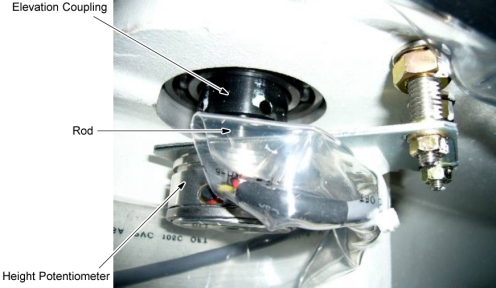
- Remove the height potentiometer from the elevation coupling according to Height Potentiometer Replacement.
- Rotate the rod of the height potentiometer to it's ClockWise limit, and then rotate back until “POT_ADJ UP” LED is ON.
- Re-install the height potentiometer.
- Confirm that the “POT_ADJ UP” LED is ON.
Figure 5. Height Potentiometer
- Using the Service Switches, move the table to the mechanical DOWN-limit position.
- Confirm that the “POT_ADJ DOWN” LED (Yellow) is ON. If it is NOT ON, adjust the height potentiometer again.
3 Finalization
Procedure
- Re-install the Table covers.