- Topic ID: id_17423124
- Version: 3.0
- Date: Dec 3, 2019 2:01:03 AM
Height Potentiometer Replacement
Prerequisites
 |
|
note: It may be necessary to lower the Table to gain access to one of the height potentiometer coupling screws. If this is done then be sure to return the Table to its highest position, and return the Gantry “Table/Tilt” switch to the OFF position.
Procedure
- Remove the left side maintenance cover from the Gantry.
- Set the service switch (MODE-SEL) to the SERVICE to enter the service mode.
- Confirm that the ”ELEV” LED on the GTCB board in
the Table is ON.
If it is NOT ON, press the “Motion Target” button until “ELEV” LED is ON.
- Upper the Table to the mechanical up limit position by the service switch (ACTION).
- Remove power from Table by turning off “120VAC”, “Axial Drive” and “HVDC” switches on the service switch panel.
- Remove the following covers and component from the Table:
-
Middle Side Cover-L (Refer to Table Covers Removal)
-
Cradle (Refer to Cradle)
-
Left and Right Rail Covers (Four(4)x2 Screws)
-
Cradle Tray (Six(6) Screws)
-
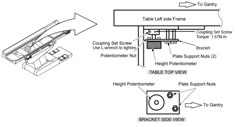
- Replace the Height Potentiometer as follows:
- Loosen the two coupling set screws.
- Remove the Potentiometer Assy together with its bracket by unscrewing the two support nuts.
- Disconnect the connector J11 from the NPCN BD Assy and feed it up through the Table.
- Remove the Height Potentiometer assy from the bracket, and mount the new Potentiometer Assy onto the old bracket.
- Install the new Height Potentiometer/bracket Assy to the Table left side frame.
- Feed the wiring of the new Potentiometer to the NPCN BD Assy and retie all the tie–wraps which were removed in Step 7.c. and Step 7.d.
- Connect the new J11 connector to the NPCN BD Assy.
Figure 1. Height Potentiometer
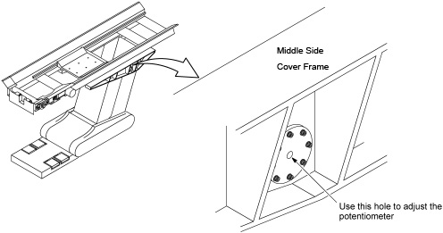
- Perform Elevation Characterization.note: Adjust the Height Potentiometer value by turning the potentiometer’s shaft with a trimmer adjuster/ tweaker (small slotted screw driver). It can be accessed through the hole in the left side cover as shown in Figure 2.
Figure 2. Height Potentiometer Adjustment
- Restore the Table to original configuration.
Finalization
No finalization steps.