- Topic ID: id_17479082
- Version: 2.0
- Date: Nov 19, 2019 11:09:29 PM
Belt Removal and Installation
Prerequisites
Overview
1 Drive Belt Removal
Procedure
- Remove the gantry covers (see gantry cover replacement procedures if needed) and lower slipring cover.
 danger
- notice
- Turn off the three (3) main power switches (Axial Drive, HVDC, 120VAC) on the gantry’s Service Switch Panel. Remove all system power at the Main Disconnect panel and use proper Lockout/Tagout procedures.
- Remove the Home Flag assembly to prevent damage.
Refer to the Home Flag and Sensor Board Assembly Replacement procedure in the menu of this publication, for details.
- Using the 5mm hex key remove the three (3) screws that secure the Drive Gear Cover, and remove the Cover.
- Rotate the tube to the 1:00 position. Do not engage the rotational lock.
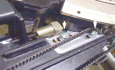
- Loosen the two (2) M12 screws with the 10mm hex key Figure 1.
- Using the 6mm hex key and the 12 inch extension, fully loosen
the elongated hex screw to remove the drive belt from the drive gear Figure 1.
Figure 1. To loosen drive belt, loosen 2 screws and the long hex screw
- Remove the drive belt from the drive gear.
- Work the belt toward the table on the rotating assembly. Keep all slack at the tube side of the gantry.
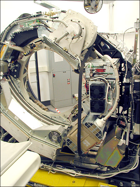
- Work the belt through the large gap to the right of the Tube,
around the inverter and to the DAS (see Figure 2).
Figure 2. Axial Drive Belt Installation/Removal Critical Path (Example)
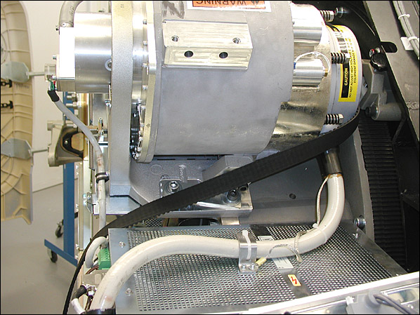
- At this point the Belt slackens. Carefully work the belt around
the rest of the rotating gantry, completing the removal process.
Figure 3. Belt Path Around Tube
 |
2 Drive Belt Installation
Procedure
- Install the Belt using the removal steps, 10 through 12, in reverse order.
- Install the Home Flag.
- Slide the Belt over the main Drive Gear and align it towards the back of the rotating assembly teeth. Check both top and bottom.
- Work the belt through the pulley tensioner assembly and place on motor drive gear.
- Tighten the elongated hex screw using a 6mm hex key and a 12 inch extension. Apply enough tension so the washer can be rotated with your fingers.
- Rotate the Gantry by hand several times and recheck tension of washer. Make sure the belt does not slip off tensioning pulley and is tracking correctly toward the rear of the gantry.
- Perform the Gantry Belt Tension Check & Adjustment procedure.
- Tighten the two (2) M12 screws using a 10mm hex key to 50 ft-lbs (66.4 N-m). This locks the tensioner assembly.
3 Gantry Reassembly
Procedure
- Install the slip ring bottom safety cover using the captive fasteners on the cover. Tighten the screws for the tilting assembly bottom cover if previously loosened when removing slip ring cover.
- Remove LOTO and restore power to the system.
- Enable 120 VAC HVDC and Axial Drive service switches from the service switch panel. Press the table drives enable button on the lower right corner of the service switch panel.
- Ensure that the Home Flag Assembly (refer to Home Flag Sensor Board Assembly Replacement) has been installed and is functioning correctly.
- Turn OFF the Axial Drive, HVDC and 120 VAC switches on the gantry’s Service Switch Panel.
- Install the gantry front, rear, top and left side covers.
Refer to Replacement → Gantry → Enclosure → (Cover Removal Procedures).
- Enable 120 VAC HVDC and Axial Drive service switches from the service switch panel. Press the table drives enable button on the lower right corner of the service switch panel.
- Install the gantry right side cover.
4 Finalization
Procedure
- Perform a [Fastcal] from the [Daily Prep] button of the scan display.
- Perform a [System Scanning Test] from the [Functional Checks] menu of the service manual to ensure system operation.