- Topic ID: id_16158072
- Version: 2.0
- Date: May 23, 2022 4:54:41 AM
CT Belt Tension Check & Adjustment (Adv)
Prerequisites
Overview
During Optima CT520 system belt replaced, there may be gantry vibrations and noise, then need FE to adjust the belt tension to achieve 500–600N.
1 Gantry preparation
Procedure
- Remove gantry right side cover.
Refer to
- Turn OFF the Axial Drive, HVDC and 120 VAC switches on the gantry’s Service Switch Panel.
- Remove the gantry left side cover, top covers, scan window and
rear cover. Connect the rear cover E-Stop cable per instructions in
cover removal to allow gantry rotation later in the procedure.note:
Turn OFF CB6 and CB3 to power OFF Gantry and Axial Drive 380V before you touch the Axial Drive.
2 Setup Belt Tension Service Tool
- (For Microphone and Belt Frequency Tool:) refer to Setup Microphone and Belt Frequency Tool (Adv)
- (For Sonic Tension Meter UNITTA U-508:) refer to Sonic Belt Tension Meter U-508 Operation Manual
3 Tension Calculation
Procedure
- Turn on gantry 120 VAC service switch from the service switch panel to allow gantry to rotate easily. Leave the Axial drive switch OFF.
- Position tube at 0 degrees (tube at top most position) while
rotating by hand in the clockwise direction.note:
Always rotate the gantry in the CW direction when checking the tension of the belt. Rotating CW and then CCW will relieve the belt tension and give inaccurate measurements.
- About measurement procedure, follow below steps.
- For Microphone and Belt Frequency Tool:
- With the microphone connected to the laptop/PC and the Belt Frequency Tool running as setup in Setup Belt Tension Service Tool, go to the gantry axial drive belt upper span near the spring tensioner assembly. Position the microphone in the middle of the upper span of the belt. Position the microphone so that it is approximately 1” away from the front of the belt without touching the belt. Position the laptop/PC so that you can see the belt tension program running.
- Lightly strum the belt (like a guitar string) while holding the microphone 1” away from the middle section of the belt. Time it so that you strum the belt immediately after a new “Acquiring data” line is written by the program. The belt frequency will be reported by the program.
note:If you do not time the measurement immediately after the “Acquiring data” line is written the results may not be reported accurately. If you continuously report “No Trigger” then strum the belt harder, move the microphone closer to the belt, or turn up your microphone volume. If you continuously report “OVERLOAD” then strum the belt softer, move the microphone away from the belt, or turn down your microphone volume. Minimize external noise as much as possible while taking measurements. Ignore false/odd readings which are most likely due to background noises fooling the program. Continue taking measurements until repeatable results are achieved.
- For Sonic Tension Meter UNITTA U-508:
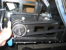
- Connect the microphone.
Figure 1. Connect the microphone

- Put the the microphone 1.5 cm away from the egde of the belt.note: Put the microphone next to the belt, keep them as close as possible but not touching.
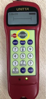
- Press MEASURE to start measurement. The green LED blinks and LCD displays |----|.
Figure 2. Green LED blink and LCD display
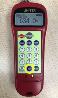
- Flip the belt. The LCD will display curves. Then result will display once peep sound emitted and green LED turns on in 1.5 s after reception of belt vibration sound.
Figure 3. Result display

- Press Hz button to switch the unit if needed.
Figure 4. Press Hz button to switch the unit
- Connect the microphone.
- For Microphone and Belt Frequency Tool:
- Take measurements with the tube positioned at 0, 90, 180, 270 degrees and record. Measurements at each tube position must be within 85 – 102 Hz which corresponds to 450 – 650 N belt tension. Average the four readings. The average must be within 89 – 98 Hz which corresponds to 500 – 600 N belt tension.
- If readings are not within spec, go to Adjusting Belt Tension and adjust belt tension. If readings are within spec, go to Finalization section in this procedure.
4 Adjusting Belt Tension
Procedure
- To unlock the tensioner assembly, loosen the two M12 screws using a 10mm hex key.
- Adjust the elongated hex screw using a 6mm hex key and a 12
inch extension. Adjust in ¼ turn increments (clockwise tightens
the belt). See Figure 5.
Figure 5. Adjust Elongated Hex Screw
- Torque the two M12 screws to lock the tensioner assembly per Table 4.
- Rotate the gantry clockwise two turns to even out the belt tension.
- Measure the belt frequency again with the tube at 0, 90, 180, 270 degrees. Continue to adjust belt and take readings until measurements are within spec.
5 Finalization
Procedure
- Restore the System Power
- Run the Gantry rotation test from Service Panel at Hispeed and Lowspeed a few times and verify that deceleration noise is acceptable.
- Disable 120 VAC, HVDC and Axial Drive service switches from the service switch panel.
- Verify that belt tension measurement is still 89 – 98 Hz.
- Install the gantry rear, top and right side covers.
Refer to
- Enable 120 VAC HVDC and Axial Drive service switches from the service switch panel.
- Install the gantry right side cover.