- Topic ID: id_17479585
- Version: 2.0
- Date: Nov 19, 2019 11:09:30 PM
Axial Drive Motor Replacement
Prerequisites
Overview
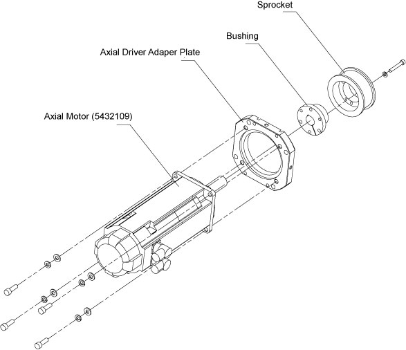
This procedure describes the steps necessary to install Axial Drive motor into the Danaher axial drive assembly. Refer to Figure 1 (Component replacement) or Figure 2 (Assembly replacement) for a visual reference of the motor.
Figure 1. Axial Drive Motor (5432109)

Figure 2. Axial Motor Kit (6489004)
1 Preparation for Replacement
Procedure
- notice
- Remove gantry right side cover and disable Axial
drive, HVDC and 120
VAC service switches from the Service Switch Panel. Remove
all system power at the Main Disconnect panel and use proper Lockout/Tagout
procedures.
For cover removal refer to Replacements > Gantry > Enclosure > Gantry Side Covers Removal and Re-install
- Perform all required LOTO activities to remove all power from the gantry.
- Remove the gantry left, top, front, and rear sub covers. Connect the cover E-stop circuit to the terminators on the gantry.
- Remove axial drive assembly.
Refer to Replacements > Gantry > Axial > Axial Drive Assembly Replacement
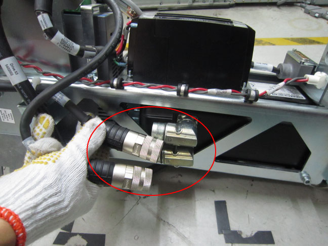
- Disconnect the power cable (5432003) and signal cable (5432004)
from the motor.
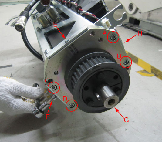
- Remove the eight screws (A~D: M6x25mm+loctite243; E~H: M6x12mm)
from the head of the bracket.
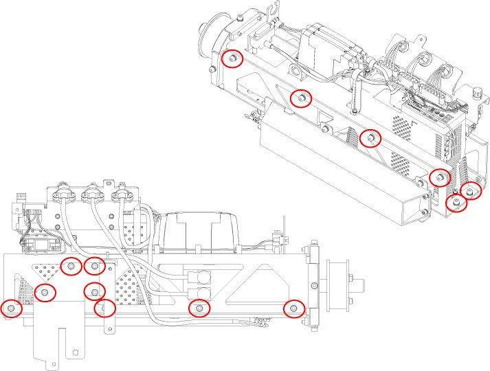
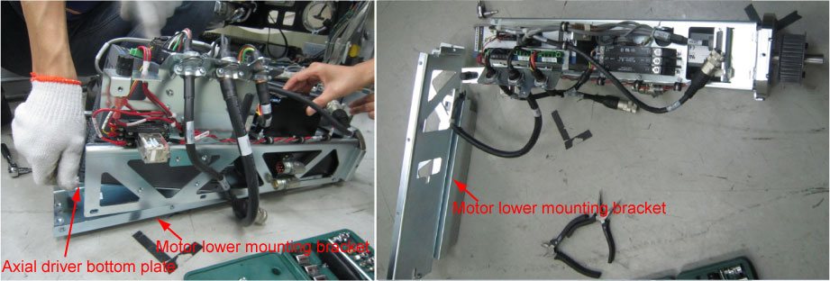
- Remove the 14xM6x12mm screws shown as below figures.
- Slide the axial driver bottom plate out of the motor lower mounting
bracket, then separate the motor lower mounting bracket from the
axial driver assembly.
 note: The axial driver bottom plate is inserted to the motor lower mounting bracket, be carefully when sliding the bottom plate out of the lower mounting bracket, as shown in below figure.
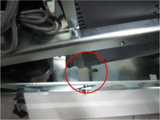
- Remove the axial motor from the motor upper mounting bracket.
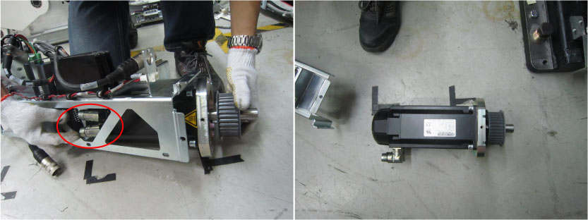
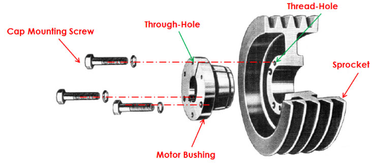
- Use 12.2 Nm standard torque wrench (type: 1/4x1–3/8, Inch) to
remove three cap mounting bolts from motor bushing, then release the
sprocket from motor bushing with rubber hummer.
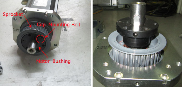
- Measure the distance from the top surface of bushing to the
head of shaft by steel tape (the distance should be 33±1mm),
fully loose the set screw and pull the bushing out, and then remove
the sprocket.note: The set screw is very small and located at great depths, use 1/8–inch L spanner to loose it.
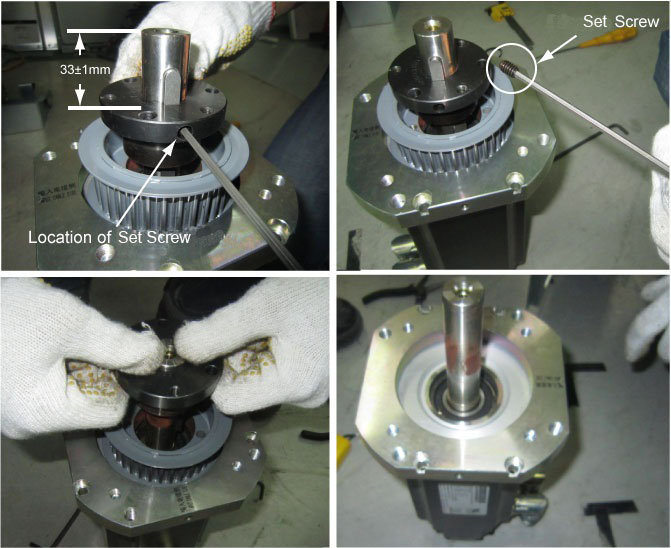
- Install the sprocket and bushing to the new motor, make sure the distance is 33±1mm between the top surface of bushing and the head of shaft.
- Adjust the sprocket three thread screw holes to the motor bushing
three through-holes, then use the three cap mounting screws cross
the though-holes and fix the sprocket to the motor bushing.
 |
note:
If select Axial Motor Kit (6489004), please ignore steps of the sprocket removal from Step 10 to Step 13 , then directly go to Installing motor on assembly frame.
2 Installing motor on assembly frame
Procedure
- Install the new motor into the axial drive assembly in the opposite order of removal.
- Secure the 14xM6x12mm screws to the axial driver assembly unscrewed in Step 7 (Torque: 7.9Nm).
- Secure the 4xM6x12mm screws to the head of the bracket (E~H) and 4xM6x25mm screws (with Loctite 243) to the head of the bracket (A~D). (Torque: 7.9Nm)
3 Cable Installation and Routing
Procedure
- Reconnect the power cable (5432003) and signal cable (5432004) to the motor.
- Reinstall the axial drive assembly to the gantry, refer to Installing Axial Drive Assembly.
- Cable installation and routing for axial drive assembly, refer to Cable Installation and Routing.
4 Reassemble gantry
Refer to Re-Assemble of Gantry.
5 Finalization
Procedure
- Run the System Scanning Test from the Functional Checks procedure list.
- “Perform a Fastcal” from the [Daily Prep] button of the scan display.