- Topic ID: id_17479118
- Version: 2.0
- Date: Nov 19, 2019 11:09:04 PM
Axial Drive Assembly Replacement
Prerequisites
Overview
This demonstrates how to replace Danaher Axial Drive assembly.
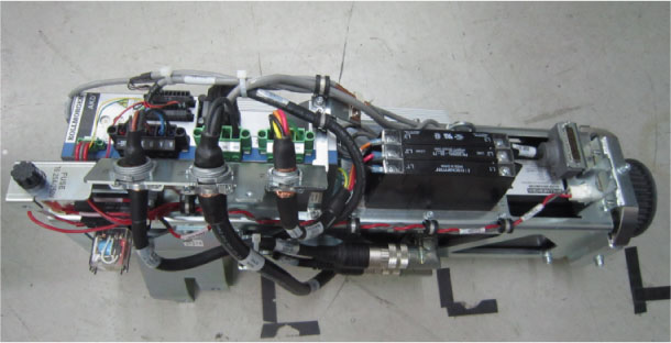
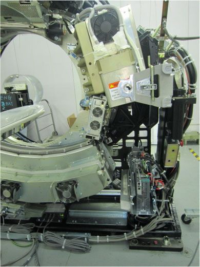
Figure 1. Drive Assembly to be installed
1 Preparation for Replacement
Procedure
- notice
- Remove gantry right side cover and disable Axial
drive, HVDC and 120 VAC service
switches from the Service Switch Panel. Remove all system power at
the Main Disconnect panel and use proper Lockout/Tagout procedures.
For cover removal refer to Replacement > Gantry > Enclosure > Gantry Side Covers Removal and Re-install.
- Perform all required LOTO activities to remove all power from the gantry.
- Remove the gantry left, top, front and rear sub covers. Connect the cover E-stop circuit to the terminators on the gantry.
- Disconnect all connections to the right options interface panel and remove the two bolts attaching the panel to the gantry.
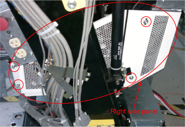
- Remove the right side panel by unscrewing its four screws for
easier access to the drive module, as shown in below figure.
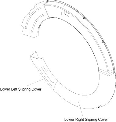
- Remove the lower (right and left) slipring covers to allow removal
of the gantry bottom cover, as shown in below figure.
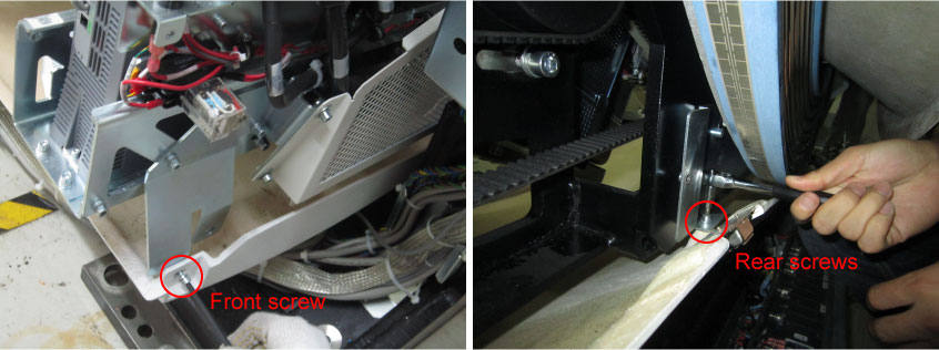
- Loosen the two front screws and remove the two rear screws of
the gantry bottom cover to allow removal of axial drive assembly,
as shown in below figure.
- Position gantry so that there are minimal obstructions from
the hoist setup to the drive/motor assembly position. See Figure 2.
Figure 2. Gantry Positioning
- Engage the rotating assembly indexer lock to prevent gantry
rotation during this procedure.note:
Be careful when removing the slipring cover. You may need to loosen the tilting base cover to aid in removal of the slipring cover. Slip Ring transmitter ring damage could occur if the cover is scraped on the ring surface.
 |
2 Removal of existing axial drive assembly
Procedure
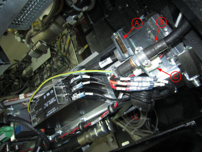
- Mark and disconnect the following cables from the axial driver
assembly. See Figure 3.
Figure 3. Cables to be disconnected.
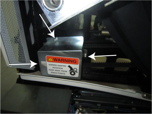
- Remove the driver pulley cover by removing the three M6 hex
screws, flat washers and washer locks. See Figure 4 below.
Figure 4. Driver Pulley Cover
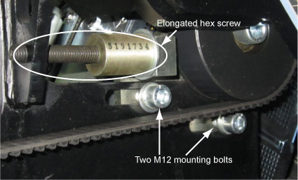
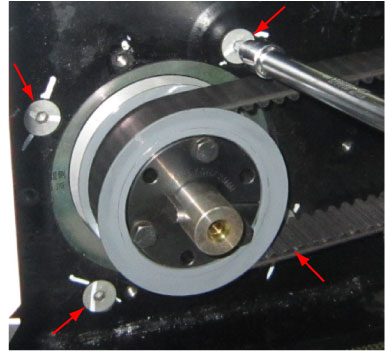
- Loosen the axial drive belt. Refer to Figure 5.
- Using a 10mm hex key, or hex bit socket, loosen the two M12
mounting bolts on the plate.note:
Loosen but do not unscrew the two M12 mounting bolts, or the belt will be tight.
- Using a 6mm hex key, or hex bit socket with a 12-in. extenstion,
fully loosen the elongated hex screw to loosen the drive belt.
Figure 5. Elongated hex screw and two M12 mounting bolts
- Using a 10mm hex key, or hex bit socket, loosen the two M12
mounting bolts on the plate.
- Remove the drive belt from the drive gear. Take care to not disturb the teeth engagement along the rotating assembly.
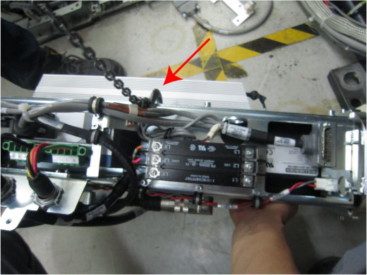
- Assemble the gantry tube hoist frame and install hoist. Clip the end of the chain to the hoist ring on the axial drive to support the drive assembly (see Figure 7 for reference).
 warning
- Using a 3/8-16 inch hex bit socket, remove the four (4) hex
screws mounting the motor to the gantry frame. See Figure 6.note:
Screws may be very tight, be careful when initially loosening motor mount screws.
Figure 6. Removing the four (4) hex screws will release motor.
- warning
- Guide the motor assembly out of the gantry and set aside. Leave the hoist assembly set up as it will be required for the installation of the new drive.
3 Installing Axial Drive Assembly
Procedure
- Attach safety cover bracket and lower Cantrell bracket onto the new drive assembly.
- Attach new drive assembly to the hoist via the hook on the middle
of the assembly side. The drive will tilt downward on the motor end
of the assembly after lifting it off the ground. See Figure 7.
Figure 7. Mounting drive assembly to hoist
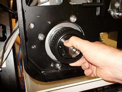
- Guide the drive into position and pivot so the drive is in correct orientation with the frame.
- Rest guide on hole in back frame, then position so bolt holes
line up. May have to pull back on drive slightly. Refer to Figure 8 below:
Figure 8. Pull back on motor hub to hold in place before bolting to frame.
- Bolt motor to frame from the back. Torque according to table.
- Remove hoist once assembly is mounted. Attach Cantrell to Cantrell
bracket if not already attached.note:
When installing the covers at the end of this procedure, it may be necessary to adjust the Cantrell to fit properly onto the front cover bracket. This is possible by turning the threaded shaft at the bottom of the Cantrell.
4 Cable Installation and Routing
Procedure
- Pull power cable through gantry frame above the motor mount.
Clamp cable in bulkhead. See Figure 9 below.
Figure 9. Routing of axial drive power cable
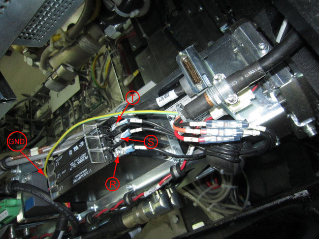
- Open the plastic cover from the terminal strip and loosen the screws on motor side of terminal strip with a cross screwdriver.
- Reconnect wires of the 380VAC power cable into terminal strip
as follows: “GND”, ”R”, “S”, “T”.
These should line up with neighbor wires from the danaher Axial Drive,
and torque according to table below. See Figure 10 for orientation
of the wires.
Figure 10. Terminal strip connections
- Tighten screws and re-install cover.
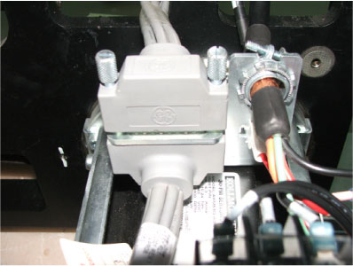
- Guide TGPG cable over bracket and connect to the Axial drive
back and tighten the two (2) Velcro straps around TGPG cable and
bracket. See illustration below.
Figure 11. Routing and connection of TGPG cable
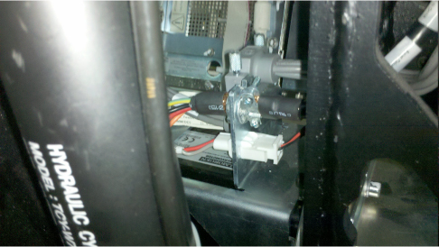
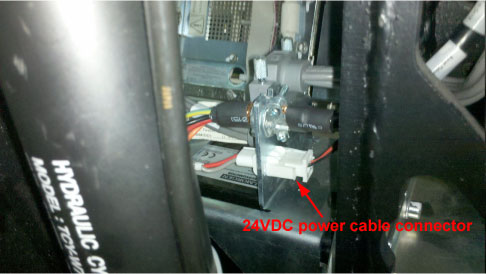
- Reconnect the 24VDC power cable connector to the axial drive
back. See Figure 12 below.
Figure 12. Connection of 24VDC power cable connector
- Replace belt around motor hub and tighten belt.
Refer to Align, Setup, Calibrations > Gantry > HP Gantry Belt Tightening Procedure.
- Secure the drive pulley cover by screwing three M6 screws and
torque according to Table below. See Figure 4 as a reference.
5 Re-Assemble of Gantry
Procedure
- Replace gantry bottom cover.
- Remove LOTO to restore system power.
- Turn on the 120 VAC service switch from the Service Switch Panel.
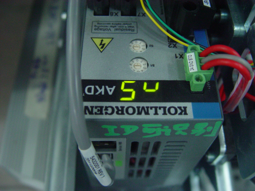
- When power is turned to ON, 3 code “n5”
"n0" "n2" should alternate display on the axial drive window. See Figure 13 below:
Figure 13. n5, n0, n2 Display in Sequence
- Turn off the 120 VAC service switch from the Service Switch Panel.
- Disengage rotating assembly lock and install the lower (right and left) slipring covers, then install the right side panel.
- Install the gantry front and rear sub covers, scan window, then the top and left side covers.
- Turn on the 120 VAC, Axial Drive, and HVDC service switches from the Service Switch Panel.
- Run gantry low speed and high speed rotation test from service
board to ensure the gantry rotating well, as shown in below figure.
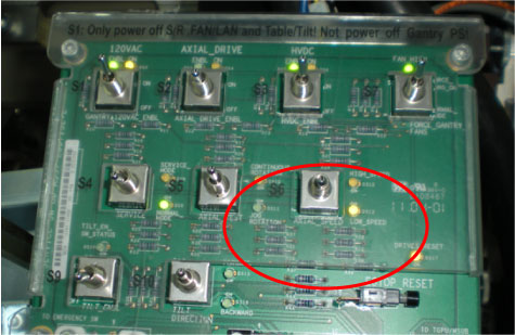
- Install the gantry right side cover.
6 Finalization
Procedure
- Perform a Fastcal from the Daily Prep button of the scan display.
- Run the System Scanning Test from the Functional Checks procedure list.