- Topic ID: BJ_211214_B01
- Version: 2.0
- Date: Dec 22, 2021 11:22:21 PM
ORP Board Replacement for PDAS
Prerequisites
Overview
This document provides the necessary steps to replace and configure the Onboard Rotation Processor Unit (ORP) for imaging.
note: If you use 5796592-2 to replace 5855016, you must order 5826006 for ORP J1 cable connection.
1 ORP Board Removal
Procedure
- Move table to its lowest position.
- Remove gantry right side cover.
- Turn off [AXIAL DRIVE ENABLE], [HVDC ENABLE] and [120 VAC ENABLE] switches on Service Switch panel.

- notice
- Remove gantry covers as required.
- Rotate gantry such that ORP assembly is in 2 o'clock position.
- Engage rotational lock.
- Put on the grounding wrist strap.
- Detach and remove cable clamps from top of ORP Assembly with a 3mm Allen Wrench.
- Cut tie-wraps holding cables to the ORP enclosure.
- Disconnect four front cables and one rear cable from ORP Assembly.
- Open the ORP enclosure cover by loosening its four screws.
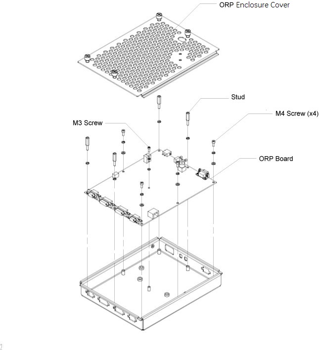
- Remove the ORP board from the enclosure by unscrewing screws and studs.
Figure 1. ORP Board Removal
2 ORP Board Installation
Procedure
- Get the new ORP board and install it to the ORP enclosure by screwing its four M4 screws and one M3 screw, apply torque to:
- M3 Screw: 1.04Nm.
- M4 Screw: 2.3Nm.
- Install four studs to the ORP board, apply torque to 2.3Nm. (See Figure 1)
- Secure the ORP enclosure cover.
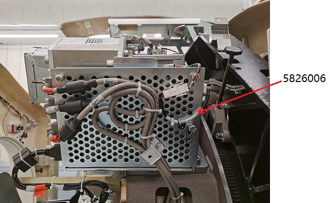
- Reconnect four front cables and one rear cable to ORP Assembly.note: If the power cable can not connect to ORP J1, please add 5826006 for cable connection, see Figure 3.
- Attach cable clamps and tie-wraps to re-tie cables to ORP enclosure cover.
Figure 2. ORP Assembly without 5826006
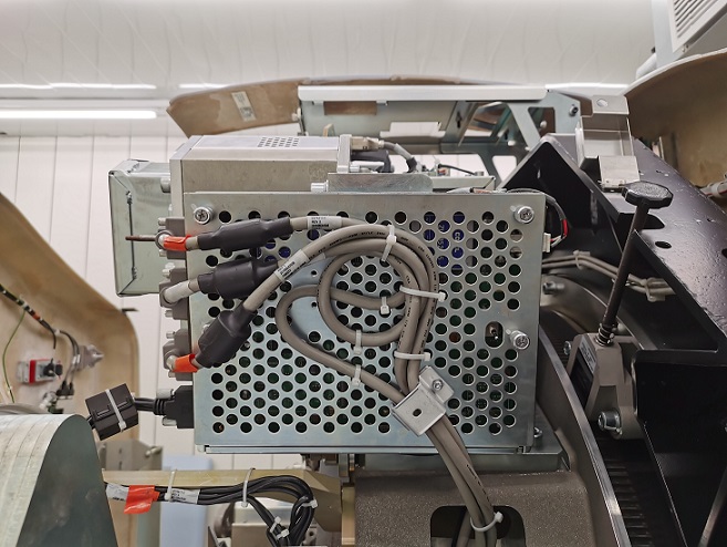
Figure 3. ORP Assembly with 5826006
- Disengage rotational lock.
- Turn on 120 VAC ENABLE, AXIAL DRIVE ENABLE, and HVDC ENABLE switches on Service Switch Panel.
- From Console Unix Shell prompt, type touch /usr/g/fw/orpFtp and press ENTER.
- Press ESTOP RESET on Service Switch panel and wait until scan hardware is reset.
3 Setup, Checks, Alignments, and Calibrations
Procedure
- Flash Download
- Gantry Rotation Safety Check
- Turn off [AXIAL DRIVE ENABLE], [HVDC ENABLE] and [120 VAC ENABLE] switches on Service Switch panel.
- Install gantry front, top and left side covers and scan window.
- Turn on 120 VAC ENABLE, AXIAL DRIVE ENABLE, and HVDC ENABLE switches on Service Switch Panel.
- Press ESTOP RESET on Service Switch panel and wait until scan hardware is reset.
- Install gantry right side cover.
4 Finalization
Procedure
- Tube Warmup
- System Scanning Test
- Save Generator Runtime Parameters (See Save Restore Generator Runtime Parameters)
- Save System State