- Topic ID: BJ_211215_B01
- Version: 2.0
- Date: Dec 22, 2021 11:22:22 PM
ORP Board Replacement for GDAS
Prerequisites
Overview
This document provides the necessary steps to replace and configure the Onboard Rotation Processor Unit (ORP) for imaging.
1 ORP Board Removal
Procedure
- Move table to its lowest position.
- Remove gantry right side cover.
- Turn off [AXIAL DRIVE ENABLE], [HVDC ENABLE] and [120 VAC ENABLE] switches on Service Switch panel.

- notice
- Remove gantry covers as required.
- Rotate gantry such that ORP assembly is in 10 o'clock position.
- Engage rotational lock.
- Put on the grounding wrist strap.
- Detach and remove cable clamps from top of ORP Assembly with a 3mm Allen Wrench.
- Cut tie-wraps holding cables to the ORP enclosure.
- Disconnect four front cables and one rear cable from ORP Assembly.
- Open the ORP enclosure cover by loosening its four screws.
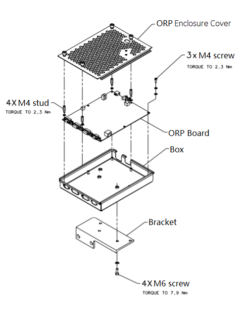
- Remove the ORP board from the enclosure by unscrewing screws and studs.
Figure 1. ORP Board Removal
2 ORP Board Installation
Procedure
- Get the new ORP board and install it to the ORP enclosure by screwing its three M4 screws, apply torque to 2.3Nm.(See Figure 1)
- Install four studs to the ORP board, apply torque to 2.3Nm. (See Figure 1)
- Secure the ORP enclosure cover.
- Reconnect four front cables and one rear cable to ORP Assembly.
- Attach cable clamps and tie-wraps to re-tie cables to ORP enclosure cover.
- Disengage rotational lock.
- Turn on 120 VAC ENABLE, AXIAL DRIVE ENABLE, and HVDC ENABLE switches on Service Switch Panel.
- From Console Unix Shell prompt, type touch /usr/g/fw/orpFtp and press ENTER.
- Press ESTOP RESET on Service Switch panel and wait until scan hardware is reset.
3 ORP Assembly Replacement
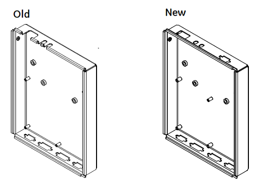
The old ORP board (2389885-3, without J11) is different with the new one, if the ORP enclosure does not match the new ORP board, refer the following steps to replace the ORP Assembly (you can find the new ORP enclosure from the Z8G4 upgrade collector B79632DA- 5877843).
Figure 2. ORP Enclosure
Procedure
- Move table to its lowest position.
- Remove gantry right side cover.
- Turn off [AXIAL DRIVE ENABLE], [HVDC ENABLE] and [120 VAC ENABLE] switches on Service Switch panel.
- notice
- Remove gantry covers as required.
- Rotate gantry such that ORP assembly is in 10 o'clock position.
- Engage rotational lock.
- Put on the grounding wrist strap.
- Detach and remove cable clamps from top of ORP Assembly with a 3mm Allen Wrench.
- Cut tie-wraps holding cables to the ORP enclosure.
- Disconnect four front cables and one rear cable from ORP Assembly.
- Open the ORP enclosure cover by loosening its four screws.
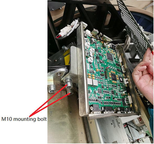
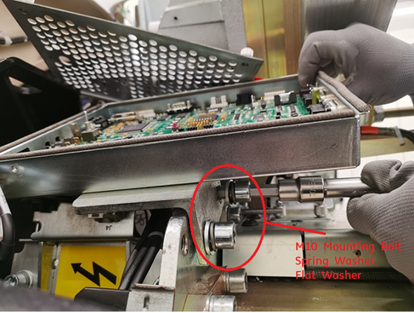
- Remove the ORP assembly from Gantry frame by unscrewing two M10 mounting bolts and washers.note: Don’t discard these bolts and washers, they will be used during re-installing.
Figure 3. Remove ORP Assembly with Bracket (example)
- Remove the ORP enclosure from the bracket by unscrewing four M6 screws.
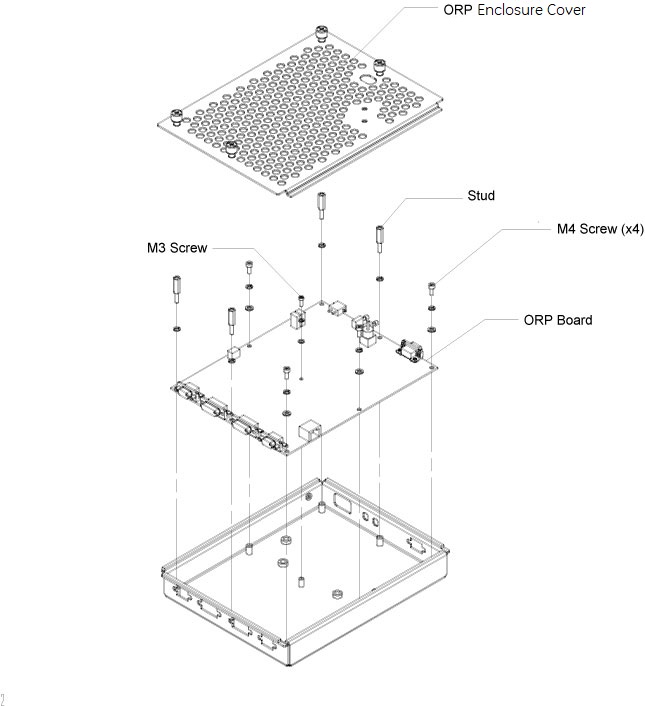
- Take out the ORP enclosure (5159044-2) and the ORP board (5796592-2) from the Z8G4 upgrade collector (B79632DA- 5877843), then assemble them by using four M4 screws and one M3 screw (see Figure 4), apply torque to:
- M3 Screw: 1.04Nm
- M4 Screw: 2.3Nm
Figure 4. Assemble ORP Board and Enclosure
- Assemble the ORP enclosure with board to the bracket by using four M6 screws, apply torque to 7.9Nm.
- Assemble the ORP assembly to Gantry frame by re-using two M10 mounting bolts with spring/flat washers, apply torque to 66.4Nm.
Figure 5. Reinstall ORP Assembly
- Install four studs to the ORP board, apply torque to 2.3Nm. (See Figure 4)
- Secure the ORP enclosure cover.
- Connect the ORP adaptive cable (5826006) to the ORP board J1.
- Reconnect four front cables and one rear cable to the ORP Assembly.
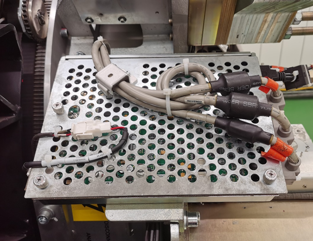
- Attach cable clamps and tie-wraps to re-tie cables to ORP enclosure cover.
Figure 6. Re-tie Cables
- Disengage rotational lock.
- Turn on 120 VAC ENABLE, AXIAL DRIVE ENABLE, and HVDC ENABLE switches on Service Switch Panel.
- From Console Unix Shell prompt, type touch /usr/g/fw/orpFtp and press ENTER.
- Press ESTOP RESET on Service Switch panel and wait until scan hardware is reset.
4 Setup, Checks, Alignments, and Calibrations
Procedure
- Flash Download
- Gantry Rotation Safety Check
- Turn off [AXIAL DRIVE ENABLE], [HVDC ENABLE] and [120 VAC ENABLE] switches on Service Switch panel.
- Install gantry front, top and left side covers and scan window.
- Turn on 120 VAC ENABLE, AXIAL DRIVE ENABLE, and HVDC ENABLE switches on Service Switch Panel.
- Press ESTOP RESET on Service Switch panel and wait until scan hardware is reset.
- Install gantry right side cover.
5 Finalization
Procedure
- Tube Warmup
- System Scanning Test
- Save Generator Runtime Parameters (See Save Restore Generator Runtime Parameters)
- Save System State