- Topic ID: BJ_211202_B01
- Version: 2.0
- Date: Dec 22, 2021 11:22:19 PM
JEDI PPC Board Replacement
Prerequisites
Overview
This procedure defines the replacement process for Programmed kV Control Board. Please check the programmed kV control board type by following the below steps before replacement.
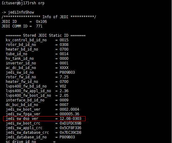
- Open a shell, type:
rsh orp
jediInfoShow
- JEDI info displays.
- If jedi_sw_dsp_ver is 12.**-****, the kV control board is SoC board.
- If jedi_sw_dsp_ver is not 12.**-****, for example: 10.**-**** or 11.**-****, the kV control board is PPC board.
Figure 1. Example for SoC Control Board
-
If possible, save JEDI runtime parameters (from JEDI to console)
-
Replace PPC board
-
Restore JEDI runtime parameters, if previously saved
-
Check functionality of systems
-
Recalibrate
1 PPC/SoC Board Removal
Procedure
- If possible, save JEDI runtime parameters (from JEDI to console).
 warning
- Remove power to the gantry using proper Lockout / Tagout procedures.
- Remove gantry right side cover.
- Turn OFF all the three switches (AXIAL DRIVE ENABLE, HVDC ENABLE, 120 VAC) on the Service Switch Panel.
- Position the inverter assembly at 2 o'clock.
- notice
- Remove largest inverter cover.
- Attach a protective ESD wrist strap.
- Disconnect wires and remove the PPC/SoC board.
 |
2 PPC/SoC Board Installation
Procedure
- Continue using the ESD wrist strap.
- Insert new PPC/SoC board and re-connect all wires.
- Replace the hex screws.
- Replace inverter cover.
3 Finalization
Procedure
- Ensure that proper torque specifications (see Torque Wrench Information) are followed for all fasteners.
- Run Flash Download Tool to synchronize PPC/SoC firmware with Console software.
- Restore JEDI Runtime Parameters, if you saved JEDI Runtime Parameters prior to replacing the PPC/SoC board (see JEDI Generator Tool (Pro16)).
- Run Meter Verification (Pro 16).
- Perform HV Tank Feedback Resistor Verification (Pro 16) (bleeder test)
- Run Filament Calibration.