- Topic ID: id_23554300
- Version: 2.0
- Date: Sep 26, 2020 10:11:36 PM
IMS Bearing Block Replacement
Prerequisites
Overview
Procedure
- Raise the Table to maximum height.
- Move the Cradle to IN limit position.
- Remove power from Table by turning off 120VAC, Axial Drive and HVDC switches on Service Switch Panel.
- notice
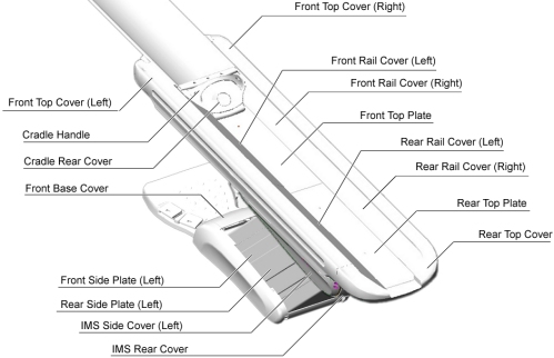
- Remove the Table covers in the following order.
-
Cradle Handle
-
Cradle Rear Cover
-
Top Cover (Right/Left)
-
Rear Top Cover
-
Rail Cover (All)
-
Top Plate (Front/Middle)
-
IMS Rear Cover
-
IMS Side Cover (Right/Left)
-
Front Base Cover
Figure 2. Table Covers
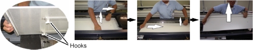
 note:Two hooks are located on the underside of the Front Top Plate. To remove the plate, raise the front end of the plate just a bit, and slide it toward the Gantry to release the hooks, then remove the plate from the Table.
Figure 3. Top Plate Removal
-
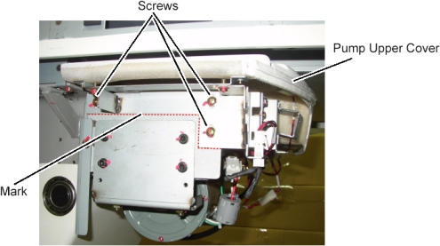
- Remove the pump upper cover as follows:
- To make reinstallation easier, mark the position of pump upper cover on both sides by outlining the edge with a marker or pencil.
- Disconnect the cable connectors of the tape switches and touch sensors.
- Remove six (6) screws holding the both sides of the pump upper
cover, and remove it.
Figure 4. Pump Upper Cover Removal
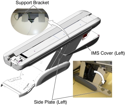
- Open the side plates as follows:
- Disconnect the GND cable from the side plate.
- Remove 2 upper support brackets of the side plates (left) by unscrewing its 2 (x2) screws.
- open the side plates as shown in illustration below.
Figure 5. IMS Cover (Left) and Side Plates (Left) Removal
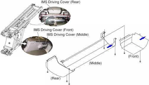
- Remove all IMS Driving Covers (Front/Middle/Rear) from the Table
as follows:
- Move the IMS to mechanical IN limit position by hand.
- Remove the IMS Driving cover (Front) by unscrewing its 2 screws.
- Remove 3 screws holding the IMS Driving cover (Middle) to the Table, and slide it toward the Gantry, then remove it from the Table.
- Move the IMS to mechanical OUT limit position by hand.
- Remove the IMS Driving cover (Rear) by unscrewing its 2 screws.
Figure 6. IMS Driving Covers Removal
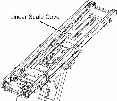
- Remove the IMS motor as follows:
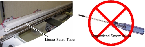
- Move the IMS to mechanical OUT limit position by hand.
- Remove the linear scale cover by unscrewing its 2 screws.
- Cut any tie-wraps holding the motor wires to the Table frame.
Figure 7. Linear Scale Cover
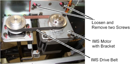
- Disconnect the motor wires connector.
- Loosen 2 screws to remove tension from the belt, and remove the belt from the pulley on the motor.
- Unscrew the 2 screws, and remove the motor with bracket.
Figure 8. IMS Motor Removal
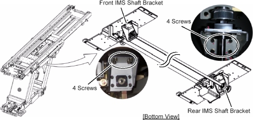
- Install 3mm shim as follows:
- note:Verify that the IMS is near the mechanical OUT limit position.
Due to the difference in size of the bearings on the new IMS bearing block, shims are needed at each connection point to ensure no interference in bearing operation.
- Loosen 4 screws holding the rear IMS shaft bracket three or four turns. (If any shim is installed on the bracket, put it back into place when installing the 3mm shim.)
- Move the IMS to mechanical IN limit position by hand.
- Loosen 4 screws holding the front IMS shaft bracket three or
four turns. (If any shim is installed on the bracket, put it back
into place when installing the 3mm shim.)
Figure 9. Location of IMS Shaft Bracket
- Move the IMS to mechanical OUT limit position by hand.
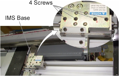
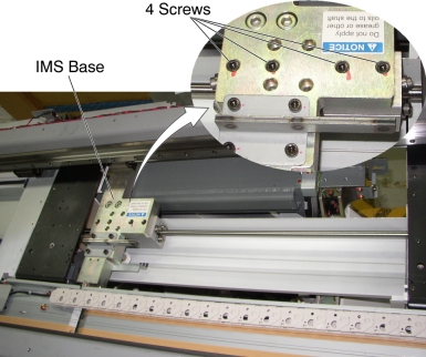
- Loosen each screw holding the IMS bearing blocks to the IMS
base.
Figure 10. Screws of IMS Bearing Blocks
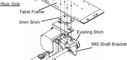
- Remove 4 screws, and install a 3mm shim between the rear IMS
shaft bracket and the Table frame, then hand tighten the screws. If
any shim is installed on the bracket, put it back into place.note:
The holes in the 3mm shim are not evenly centered. The portion with more space between holes and edge of shim goes to the back of the Table.
Figure 11. 3 mm Shims Installation (Rear Side)
- Move the IMS to mechanical IN limit position by hand.
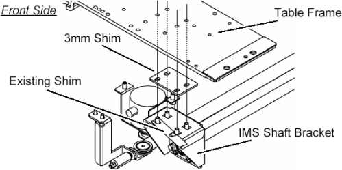
- Remove 4 screws, and Install a 3mm shim between the front IMS
shaft bracket and Table frame, then hand tighten the 4 screws. If
any shim is installed on the bracket, put it back into place.note:
The holes in the 3mm shim are not evenly centered. The portion with more space between holes and edge of shim goes to the back of the Table.
Figure 12. 3 mm Shims Installation (Front Side)
- Remove two IMS bearing blocks as follows:
- note:Remove 4 screws.
The present configuration of two bearing blocks will be replaced by one new bearing block.
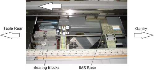
Figure 13. Bearing Blocks Disengagement
- Move the IMS to OUT limit position by hand.
Figure 14. IMS Base and Bearing Blocks
- Turn up the underside of the bearing block.
Figure 15. Underside of the Bearing Block
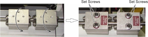
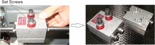
- note:Loosen alternately two set screws of one of bearing blocks holding the bearing block to prevent falling from IMS shaft, and remove the set screws, then remove the bearing block from the IMS shaft.
Take care not to drop screws, washers or spring to the inside of Table.
Figure 16. IMS Bearing Block Removal
- Remove the other bearing block in a similar way.
- Install new bearing block as follows:
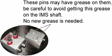
- notice
- Wipe up a IMS shaft with dry paper towels or equivalent.
- notice
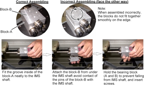
- Attach a new bearing block to IMS shaft, and finger tighten
alternately two set screws.
Figure 18. Bearing Block Attachment
- Alternately rotate the two set screws evenly, a little at a
time so that there is approximately 5mm between the bottom of the
washer and the base of the bearing block as illustration below. This
is a preliminary tension adjustment for the bearing block and will
be re-adjusted later in the procedure.
Figure 19. Bearing Block Installation


- Adjust the position of IMS shaft as follows:
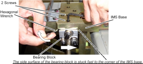
- Engage the bearing blocks to the IMS base as follows:note:
The adjustment of bearing block tension is performed after completion of IMS shaft alignment.
-
Put a 3mm shim on the bearing block, and move the IMS so that the IMS base is over the bearing block.
Figure 20. New Bearing Block and 3 mm Shim
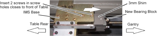
-
Push the bearing block against the corner of the IMS base using the hexagonal wrench, and tighten two screws (Torque: 9.1Nm / 92.8kgf.cm / 6.7lbf.ft).
Figure 21. Bearing Block Engagement
-
- IMS Shaft Alignment as follows:note:
The following process of loosening the ends, moving the IMS and retightening, repeatedly is designed to relieve stress on the IMS shaft by allowing to find it's true position.
-
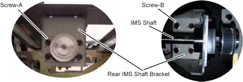
Loosen 4 screws (Screw-A) so that the rear end of IMS shaft can be slid by hand. (The screws should hold the shaft in place, but allow movement if needed.)
-
Move the IMS to mechanical IN limit position by hand.
-
Loosen 4 screws (Screw-B).
-
Hand-tighten the 4 screws (Screw-B).
-
Hand-tighten the 4 screws (Screw-A).
Figure 22. Rear End of IMS Shaft and IMS Bracket
-
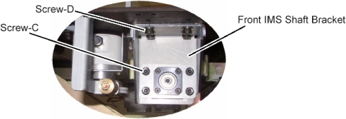
Loosen 4 screws (Screw-C) so that the front end of IMS shaft can be slid by hand. (The screws should hold the shaft in place, but allow movement if needed.)
-
Move the IMS to mechanical OUT limit position by hand.
-
Loosen 4 screws (Screw-D).
-
Hand-tighten the 4 screws (Screw-D).
-
Hand-tighten the 4 screws (Screw-C).
Figure 23. Front End of IMS Shaft and IMS Bracket
-
Repeat 12.b.i to 12.b.x two more times, and fix both ends of the IMS shaft bracket, screws B and D (Torque: 11Nm / 115kgf.cm / 8.1lbf.ft) and both ends of the IMS shaft, screws A and C (Torque: 7Nm / 70kgf.cm / 5.2lbf.ft).
-
- Engage the bearing blocks to the IMS base as follows:
- Install new IMS motor as follows:
- Install the new motor in place, and position the belt on and around the motor pulley.
- Tighten the 2 screws, to fasten the motor, with tension on the belt.
- Adjust belt tension according to IMS Belt Tension Adjustment.
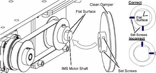
- Install the clean_damper to the IMS motor shaft.note:
The purpose of clean damper is to absorb the vibration from IMS drive which may be increased by IMS bearing change.
Do not position the set screws of clean_damper on each flat surface of IMS motor shaft.
Figure 24. Clean Damper Installation
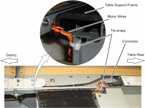
- Re-connect the motor wires connector, and route the motor wires
from the side edge of the Table support frame (red dotted line) as
shown in illustration below, then fasten the wires to the Table frame
with tie-wraps.
Figure 25. IMS Motor Cable Wiring
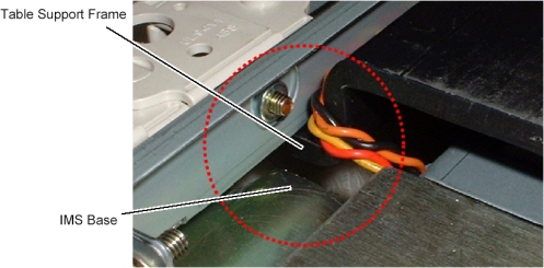
- Move the IMS to mechanical IN limit position by hand, and verify
that the motor wires are not caught between the IMS base and the Table
support frame.
Figure 26. Table Support Frame and IMS Base
- Re-install the linear scale cover.
- Adjust IMS bearing block tension according to IMS Belt Tension Adjustment.
-
(For GT1700) Replace IMS Stopper, Sensor Bracket
and Rear Touch Plate as follows:
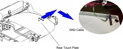
- Slide the rear touch plate away from the Gantry, to release the inside hook of the plate, and remove the touch plate.
- Disconnect the GND cable from the rear touch plate.
Figure 27. Rear Touch Plate Removal
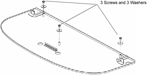
- Remove 3 screws and washers from the removed rear touch plate,
and transfer them to new rear touch plate.
Figure 28. New Rear Touch Plate
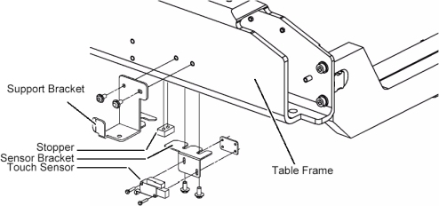
- Unscrew the 2 screws, and remove the support bracket from the Table frame.
- Unscrew the 2 screws, and remove the stopper from the Table frame.
- Unscrew the 2 screws, and remove the touch sensor from the sensor bracket.
- Unscrew the 2 screws, and remove the sensor bracket from the
Table frame.
Figure 29. Brackets Replacement
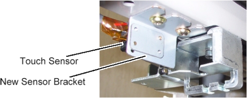
- Install the new sensor bracket into place.
- Attach the touch sensor to the new sensor bracket.
Figure 30. New Sensor Bracket
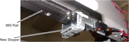
- Install the new stopper into place, and push the stopper against
the IMS rail, then tighten two screws (Torque: 11Nm / 115kgf.cm /
8.1lbf.ft). (The purpose of this replacement is to protect the Linear
Guide.)
Figure 31. New Stopper
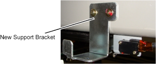
- Install the new support bracket into place.
Figure 32. New Support Bracket
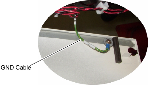
- Connect the GND cable to new rear touch plate, and install it
to the Table.
Figure 33. GND Cable of Rear Touch Plate
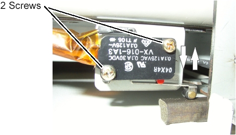
- Adjust the position of the touch sensor as follows:
-
Loosen 2 screw of the touch sensor.
-
Hold down the touch sensor to activate it, and push up the touch sensor until the sensor is released, then tighten the 2 screws.
Figure 34. Touch Sensor Positioning
-
- Push and free the touch plate several times, and verify that the touch sensor is operating normally.
-
(For GT2000) Replace the stopper as follows:
- Unscrew the 2 screws, and remove the stopper from the Table frame.
- Install the new stopper into place, and push the stopper against
the IMS rail, then tighten two screws (Torque: 11Nm / 115kgf.cm /
8.1lbf.ft).
Figure 35. New Stopper
|
Finalization
- Re-install the following covers:
IMS Driving Cover (Rear)
Pump Upper Cover
- Power up the Table from the service Switch Panel in Gantry.
- notice
- Move the cradle and IMS in and out completely 10 cycles and verify that table movement is operating normally.
- Re-install the following covers in the following order.
IMS Driving Cover (Middle)
IMS Driving Cover (Front)
Front Top Plate
Rear Top Plate
Rail Covers
Cradle Rear Cover
Cradle Handle
- Re-install the rest of the Table covers.
- Raise and lower the table a couple times and verify that table movement is operating normally.