- Topic ID: id_23553958
- Version: 3.0
- Date: Nov 27, 2020 2:07:39 AM
IMS Belt Tension Adjustment
Prerequisites
Overview
- (For Sonic Tension Meter UNITTA U-508:) refer to Sonic Belt Tension Meter U-508 Operation Manual
Procedure
- Raise the table to maximum height.
- Move the cradle and IMS to out limit position.
- Remove power from the table by turning off 120VAC, Axial Drive and HVDC switches on Service Switch Panel.
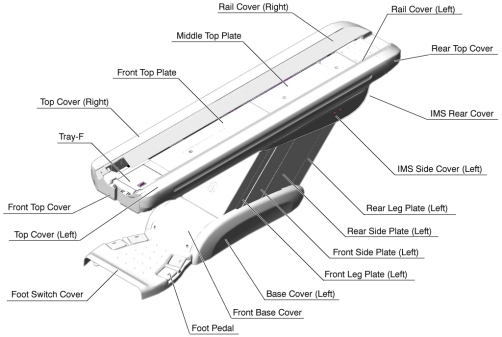
- Remove the following Table covers:
-
Top Cover (Right/Left)
-
IMS Side Cover (Right/Left)
-
IMS Cover Rear
Figure 1. Table Covers
-
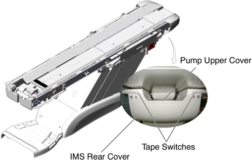
- Disconnect the cable connector of the tape switch.
Figure 2. Tape Switches
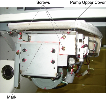
- Remove the pump upper cover as follows:
- To make re-installation easier, mark the position of pump upper cover on both sides by outlining the edge with a maker or pencil.
- Disconnect the cable connectors of the tape switches and touch sensors.
- Remove six (6) screws holding the both sides of the pump upper
cover, and remove it.
Figure 3. Pump Upper Cover Removal
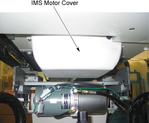
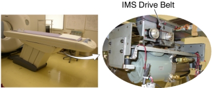
- Remove IMS motor cover.
Figure 4. IMS Motor Cover, IMS Drive Belt
- If the clean damper is mounted on the IMS Motor Shaft, it will
need to be removed to access the IMS Drive Belt. Remove the clean
damper by loosening the two setscrews on the backside of the clean
damper. Note the orientation of the setscrews on the shaft for replacement.
Figure 5. Clean Damper
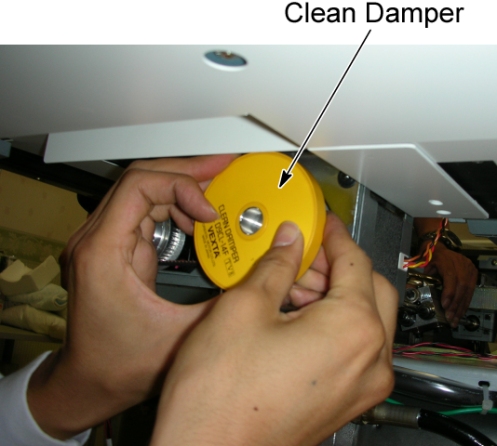
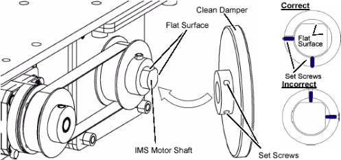
Figure 6. Clean Damper Installation
- Hold the tension meter sensor half way on the middle of the
upper side of belt, and lightly strum the top of the IMS belt in the
middle of the belt span to make it vibrate. Measure the frequency
and procedure.note:
The closer the meters sensor is to the belt without touching, the better the reading will be.
A waveform graphic will show up on the LCD screen. After the signal is processed properly, the belt frequency will appear on the screen and a successful measurement on the Gates meter will beep 3 times, and the green LED turns on steady to indicate a successful reading.
Adjust Belt Tension in small increments. If the frequency is high, loosen the belt. If the frequency is low, tighten the belt.
- Compare measurement value to the IMS belt frequency spec of (Between 100 and 140 HZ).
- If frequency is out of spec, proceed to the following sub steps:
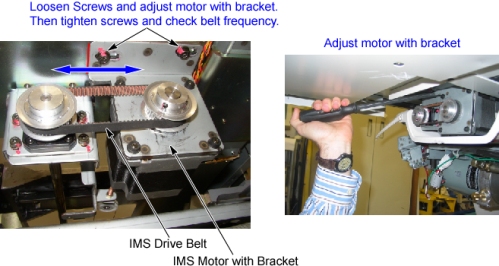
- Loosen 2 screws on IMS motor bracket. Tighten belt by using
flat head screwdriver to push motor bracket assembly. Tighten 2 screws
securely while keeping tension on the belt.
Figure 7. IMS Belt Tension Adjustment
- Continue to adjust belt and measure frequency until it is within spec.
- Loosen 2 screws on IMS motor bracket. Tighten belt by using
flat head screwdriver to push motor bracket assembly. Tighten 2 screws
securely while keeping tension on the belt.
- If you removed the clean damper earlier in the procedure, please re-install it on the IMS Motor Shaft. Please refer back to step Step 8 for proper installation.
- IMS belt adjustments are complete at this time. IMS covers can be re-installed at this point.
Finalization
- Power up the table from the service Switch Panel in gantry.
- Move the cradle and IMS in and out completely 10 cycles, and verify that table movement is operating normally.
- Remove power from the table by turning off 120VAC, Axial Drive and HVDC switches on Service Switch Panel.
- Re-install the Table covers.