- Topic ID: id_23554607
- Version: 2.0
- Date: Sep 26, 2020 10:11:49 PM
Hercules Coolant Air Removal Procedure
Prerequisites
Overview
The high voltage coolant system consists of the Heat Exchanger, Oil Pump, and X-Ray Tube. By definition this is a closed system. However events can occur that introduce air into this system. This can result in unusual Image Artifacts and/or tube over temperature issues. This procedure can prevent the need to replace the Heat Exchanger, Oil Pump, and X-Ray Tube components.
1 Frequently Asked Questions
Procedure
-
Q: Can I use silicone-based oil in this procedure?
A: NO. The part number for oil is included in this procedure and you may not deviate.
-
Q: Can I use this tool and procedure for water
based coolant systems (MCS 7079 tubes)?
A: NO. Use kit number 5115466, Performix Pro Purge Kit. Introducing water-based coolant into this tool will require replacement of the Heat Exchanger, Oil Pump, and X-Ray Tube, as a complete set. Additionally this tool will need to be scrapped. Do not contaminate with water-based coolants.
-
Q: How often should this procedure be performed?
A: There is no standard answer. It is recommended that this procedure be performed when the Heat Exchanger Compensation procedure is done, approximately every third tube change. This procedure can also be used for troubleshooting when unusual Image Artifacts or tubes over temperature issues exist.
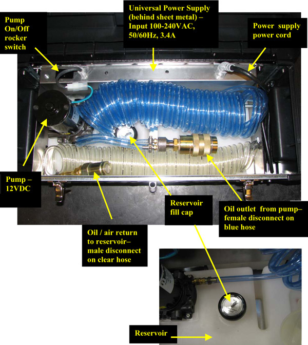
2 Major Components of the Air Removal Kit
3 Procedure
Procedure
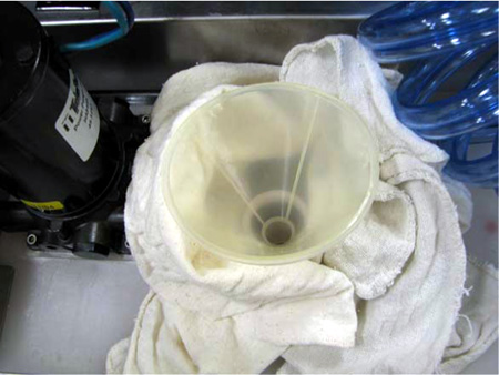
- Remove the reservoir cap and place funnel into tank. Place rags around
funnel to capture any spilled oil.
Figure 1. Funnel and Spill Rags
- Fill reservoir with approximately 1 US gallon of transformer oil, part
number T0552G.
-
At a minimum, make sure the reservoir is 1/2 full prior to starting the air removal procedure.
-
The reservoir’s volume is approximately 5 liters (1.3 gallons).
-
- notice
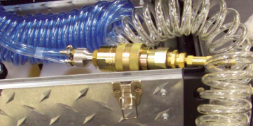
- Connect the female and male disconnects as shown.
Figure 2. Connect female and male disconnects
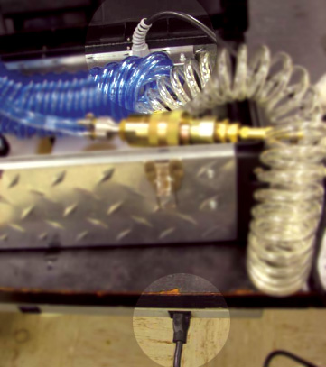
- Plug in the power supply.note:
The power supply as shown is set up for 115V operation. However, it is a universal power supply and will work internationally with the correct interface adapter.
Figure 3. Plug in the power supply
- Turn ON the power to the pump by actuating the rocker switch.note:
Oil will flow through the large blue hose into the clear hose. Some incidental back flow through the small blue hose is expected as well.
- When all air is out of the large blue hose (~ 30 seconds), shut OFF the pump, and disconnect the quick disconnects.
 caution
- Remove the bolts that hold the quick disconnect collars in place around
the disconnects, at locations A and B (already removed at location B). Do
this with the gantry rotated into a convenient position to do the work, tube
at 1-2 o’clock.
Figure 4. Remove Quick Disconnect Collars
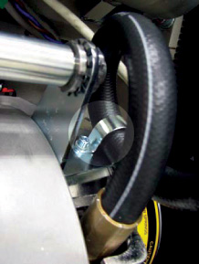
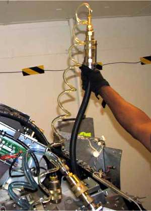
- Remove the bracket that holds the tube hose in a coiled position and
straighten the hose.note:
Use this picture as reference of how to properly coil the hose upon completion of air removal process.
Figure 5. Coiled Tube Hose
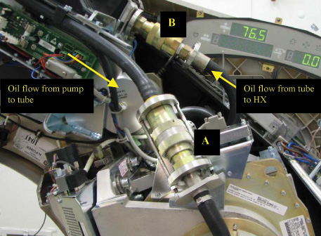
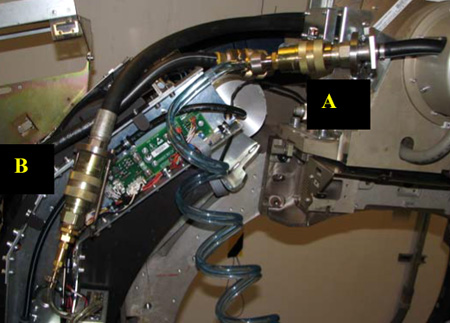
- Disconnect the quick disconnects at locations A and B.
Figure 6. Uncouple Quick Disconnects
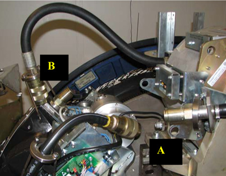
- Connect the female disconnect from the air removal kit to the tube male
disconnect at location A (see Figure 7).
Figure 7. Connect Air Removal Kit
- Connect the male disconnect from the air removal kit to the tube female disconnect at location B (see Figure 7).
- Plug in the power supply for the air removal kit.
- Ensure the air removal kit reservoir is at least 1/2 full.
- Turn ON the air removal kit pump using the rocker on/off switch. Keep the pump running for the duration of Step 15 through Step 17.
- While periodically raising the clear oil return line, allow the air
removal pump to run for 1-2 minutes.note:
Raising the return line allows air in the system to rise to the highest point for easy air removal.
Figure 8. Raise the Line to Help Air Escape
- With the gantry unlocked, gently rotate the gantry so that the tube is in approximately the 4-5 o’clock position. Hold this position for 1-2 minutes. Again periodically raise the return line to allow air to escape.
- Rotate the gantry so that the tube is in approximately the 7-8 o’clock position. Hold this position for 1-2 minutes, raising the return line periodically.
- caution
- Repeat Step 16 and Step 17 a minimum of three (3) times. However, if air continues to be removed, keep repeating until air is no longer being visibly removed.
- Turn OFF power to the air removal pump.
- Remove the air removal quick disconnects from the tube.
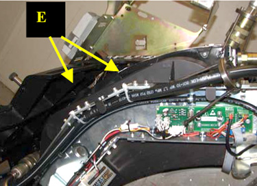
- Cut the tie wraps holding the pump hose in the heat exchanger channel,
shown in E. Be careful not to cut the hose.
Figure 9. Cut Tie Wraps
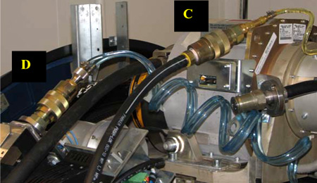
- Ensure the air removal kit reservoir is at least 1/2 full.
- Connect the air removal kit to the disconnects of the oil pump and heat
exchanger as shown in C and D.
Figure 10. Connect Air Removal Kit to Oil Pump & Heat Exchanger
- Repeat Step 14 through Step 18, applied to the heat exchanger.
- When air removal process is complete, the heat exchanger bellows is filled to capacity. Therefore, the coolant circuit must be compensated according to the Heat Exchanger Compensation (VCT, Pro) procedure.
 |
 |
Air removal will be done on the components separately: first the tube, and then the pump and heat exchanger together.
4 Finalization
Procedure
- Perform the Hercules Coolant Flow Rate Measurement procedure.