- Topic ID: id_23554170
- Version: 1.0
- Date: Oct 9, 2018 1:40:13 PM
Gantry New Balance Sensor Hardware Replacement
Prerequisites
Overview
This procedure defines the steps necessary to replace the gantry balance sensor hardware.
1 Gantry Setup for replacement
Procedure
- Drive the table to its full back position and position it full up if not already there.
- Remove gantry right side cover.
Refer to
- Turn off 120 VAC, Axial Drive and HVDC Service Switches.
- Remove the Gantry left side, the front cover can stay connected to the gantry cables, just needs to be moved away from the gantry toward the table..
- Set up Field ESD strap connecting it to a gantry ground point. Wear the strap when replacing any of the gantry balance circuit boards in the following sections.
2 Part Replacement
Procedure
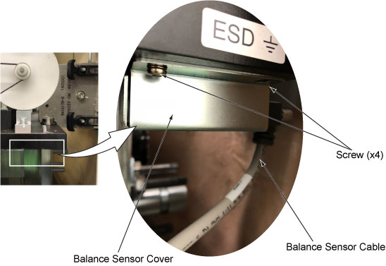
- Remove the cable connector from the balance sensor board.
- Remove the balance sensor cover with the circuit board from
the Gantry Frame by unscrewing four (4) screws
Figure 1. Balance Sensor Assy
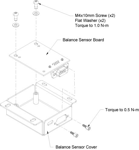
- Remove the defective circuit board from the cover by unscrewing
two (2) screws, then install the new one to the cover.
Figure 2. Balance Sensor Board Replacement
- Reinstall the balance sensor cover with the circuit board to the Gantry Frame.
- Reconnect the cable connector to the balance sensor board.
- Turn on the gantry 120VAC service switch and press the table drives enable at the lower right corner of the service switch panel.
- Return the gantry to a zero tilt position using switch S10. Then turn Tilt Enable S9 to Off and put the Service Mode switch in the down position.
- Turn the 120VAC service switch off.
- Reinstall the tilting assembly side safety panel. (5 mm hex wrench)
3 Sensitivity Matrix
Procedure
- At the console, go to the Service Desktop and select Shell from the Utilities tab.
- Type the following command line to remove the current sensitivity
matrix and exit the shell.
rm /usr/g/fw/sensmatrix.dat
exit
4 Finalization
Procedure
- Perform Gantry Service balance from the Common Service Desktop Calibrations Tab. This procedure will have you install the gantry balance trial weights to create a new sensitivity matrix. Reference the Gantry Balance Procedure if needed.
- Reinstall gantry left side cover.
Refer to
- Turn on the gantry 120 VAC, HVDC and Axial drive service switches.
- Install the gantry right side cover.
- Run the System scanning test from the Functional Checks procedure list.